
(1) Optimized profile modification of large and small gears+drum profile modification of tooth direction
Figures 1, 2, 3, 4 and 5 respectively show the combined modification of large and small gear tooth profile, the combined modification of large and small gear long tooth profile tooth top involute plus tooth drum, the combined modification of large and small gear long tooth profile tooth top arc plus tooth drum, the combined modification of large and small gear long tooth profile tooth top broken arc plus tooth drum, and the combined modification of large and small gear long tooth profile tooth top linear plus tooth drum. By observing the above five figures, it can be found that although there are composite optimization modification schemes that reduce the transmission error of the helical gear pair, these schemes are all at the cost of sacrificing the strength of the helical gear, i.e. increasing the Hertz contact stress, so they are all discarded.
(2) Optimized profile modification of large and small gears+drum profile modification of a certain gear
Figures 6, 7, 8, 9 and 10 show the drum modification of the large and small gear tooth profile plus the drum modification of a helical gear tooth, the involute modification of the large and small gear long tooth profile plus the drum modification of a helical gear tooth, the circular arc modification of the large and small gear long tooth profile plus the drum modification of a helical gear tooth, the circular arc modification of the large and small gear long tooth profile plus the drum modification of a helical gear tooth Linear modification of the tooth top of the large and small gears with long tooth profile plus drum modification of the tooth direction of a helical gear. From the above five figures, it can be found that the shape modification effect of the other schemes is generally poor, except that the transfer error and Hertz contact stress of the two No.1 schemes in Fig. 8 (a) and (b) are reduced compared with the unmodified ones. However, after in-depth analysis of the above two optimized modification schemes (as shown in Figure 10), the transmission error and Hertz contact stress are increased compared with those before the composite modification, which is meaningless except for the cost increase, so it is omitted.
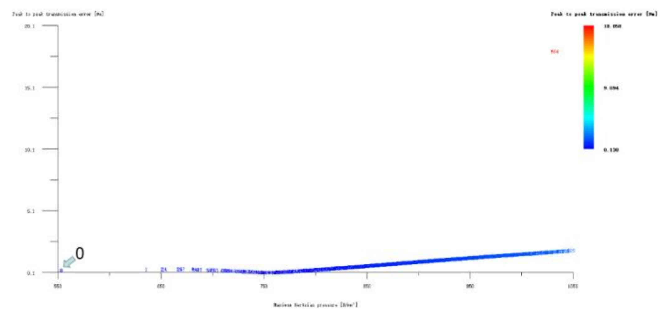
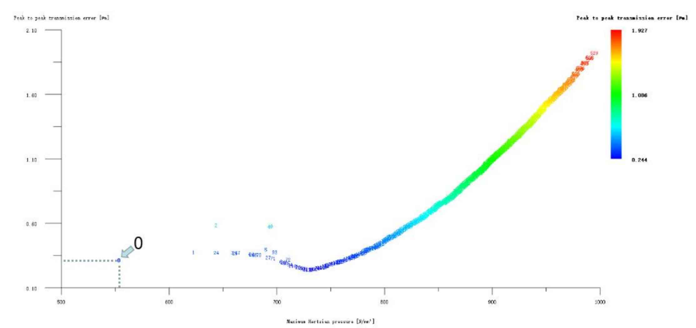
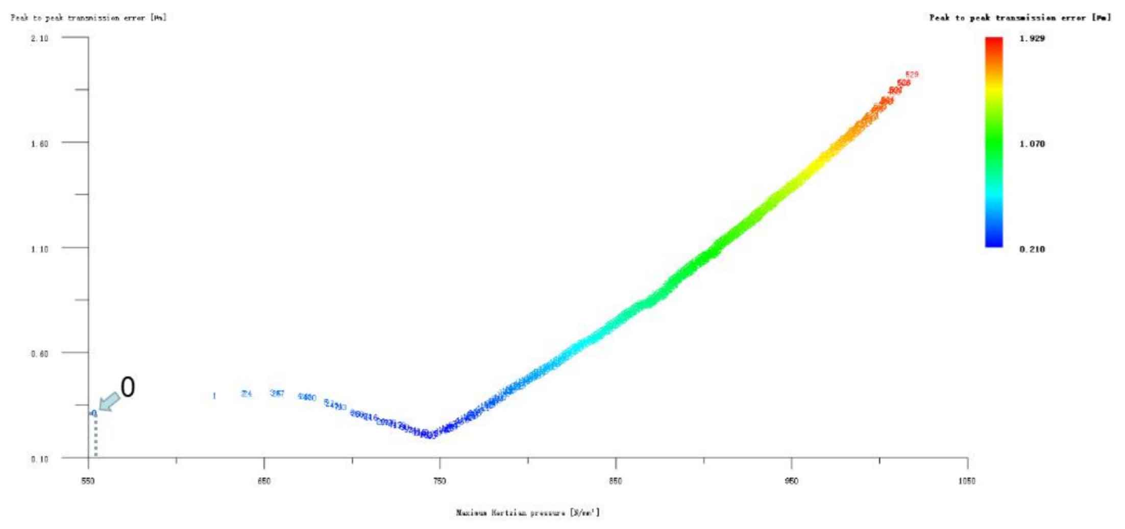
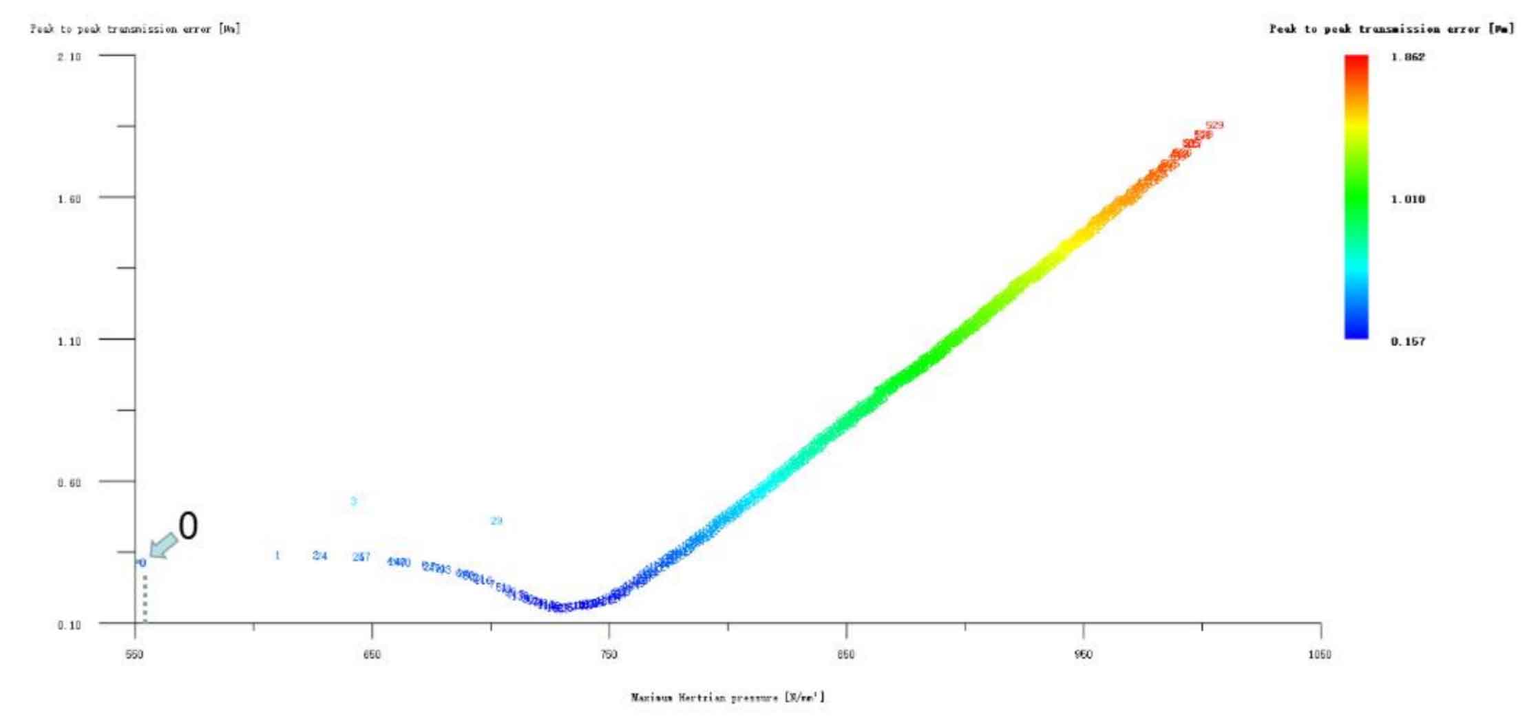
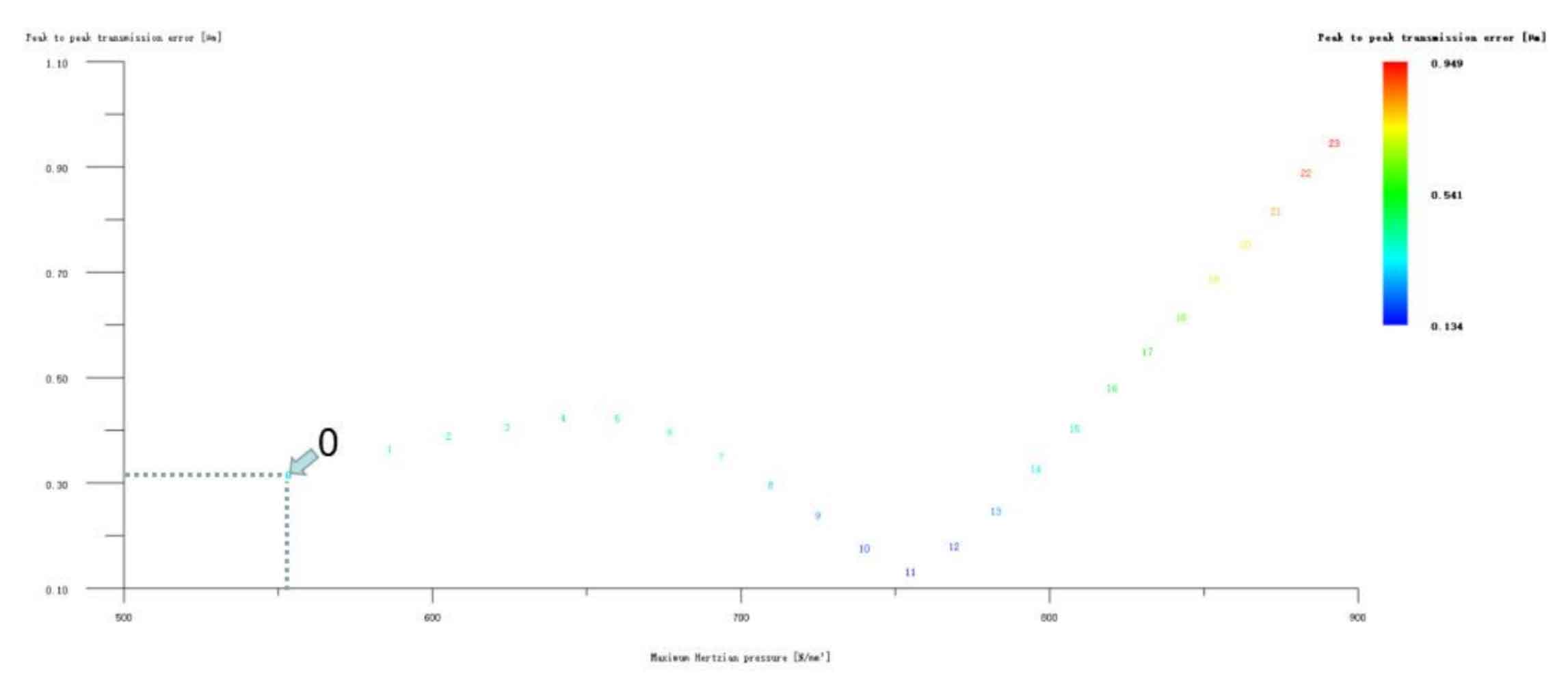
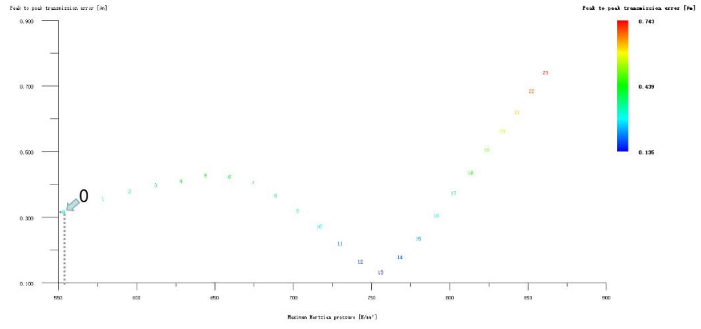
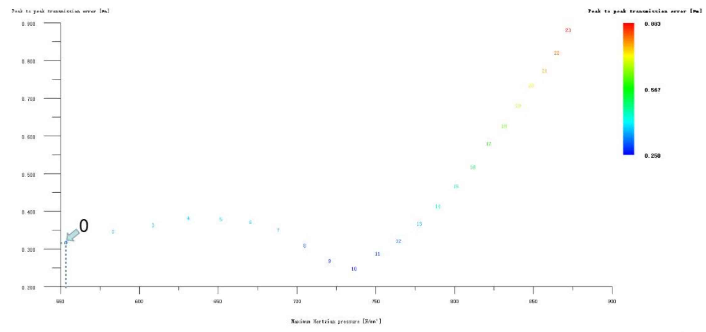
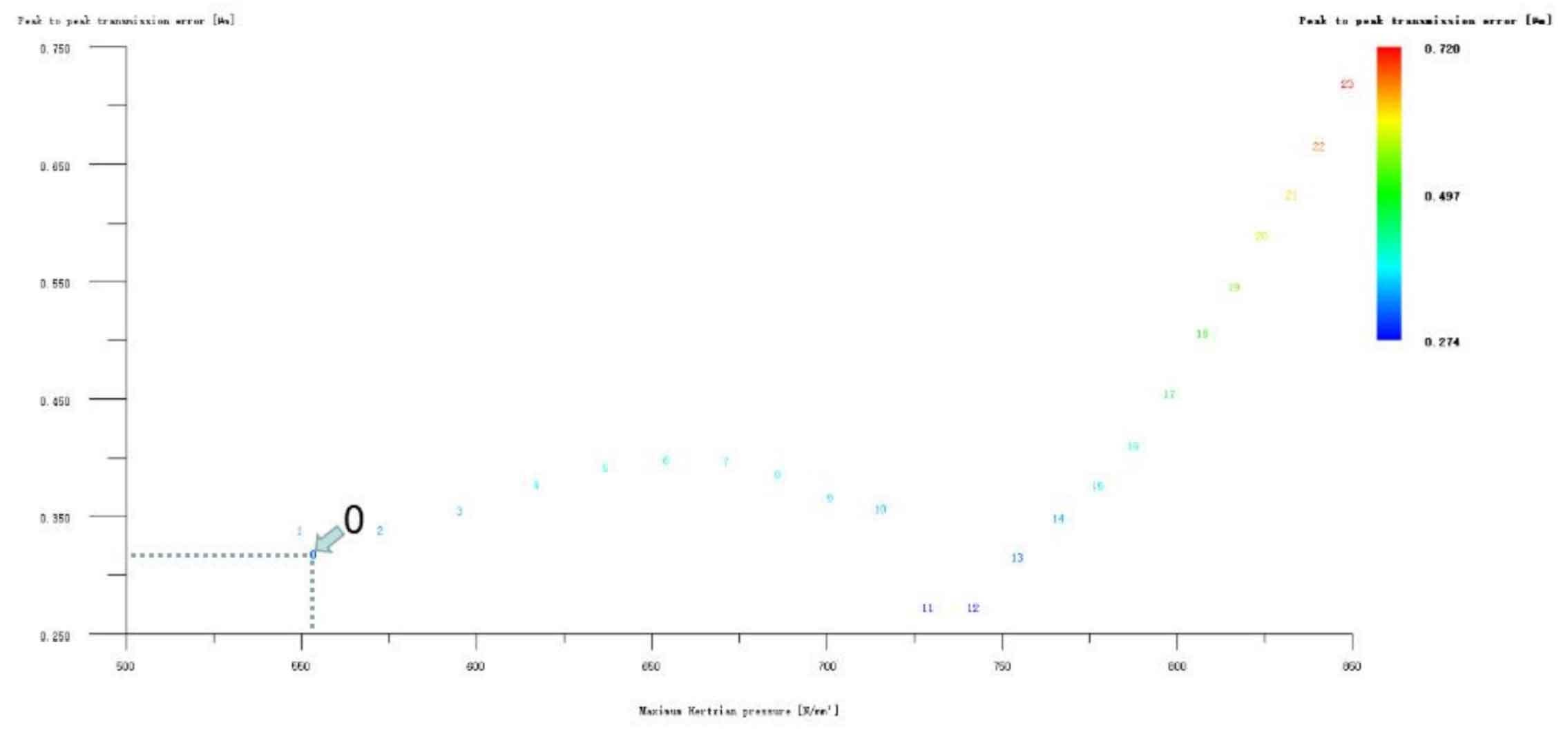
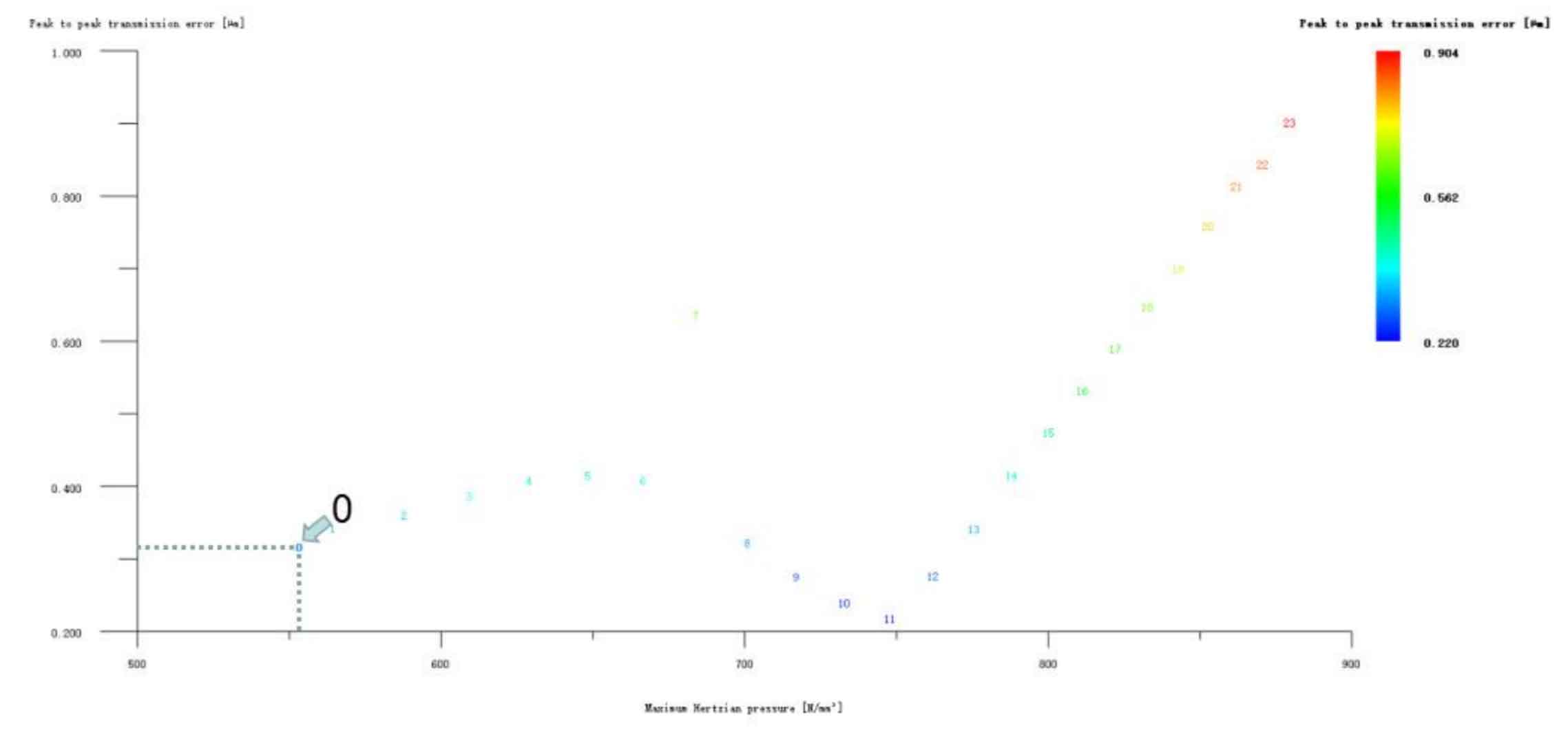
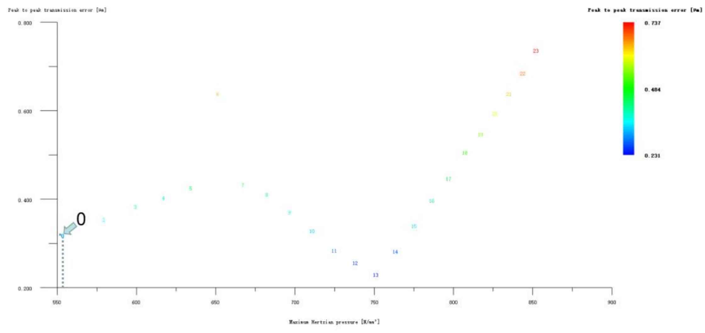
(3) Optimized profile modification of single gear+drum profile modification of tooth direction
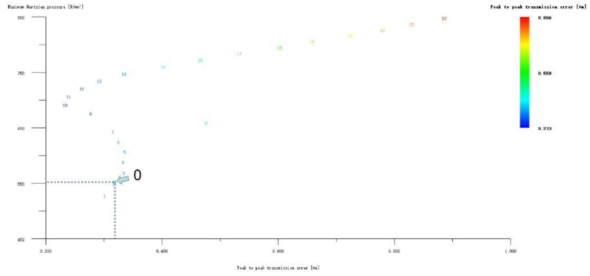
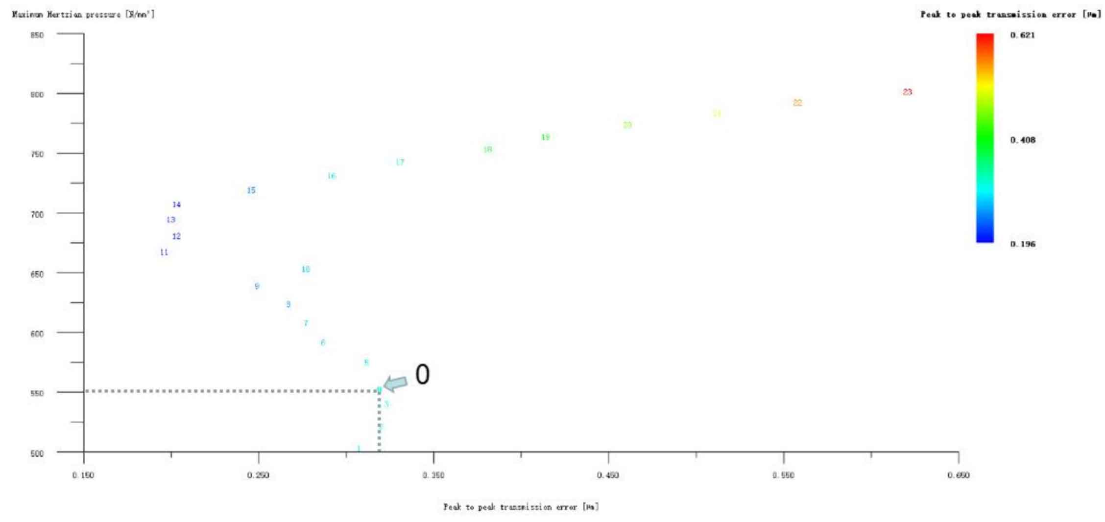
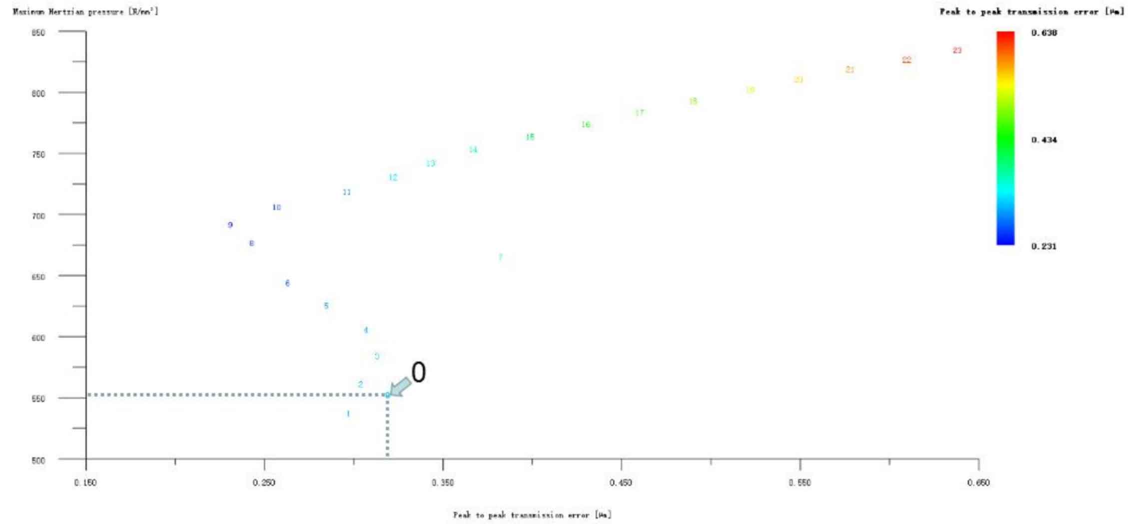
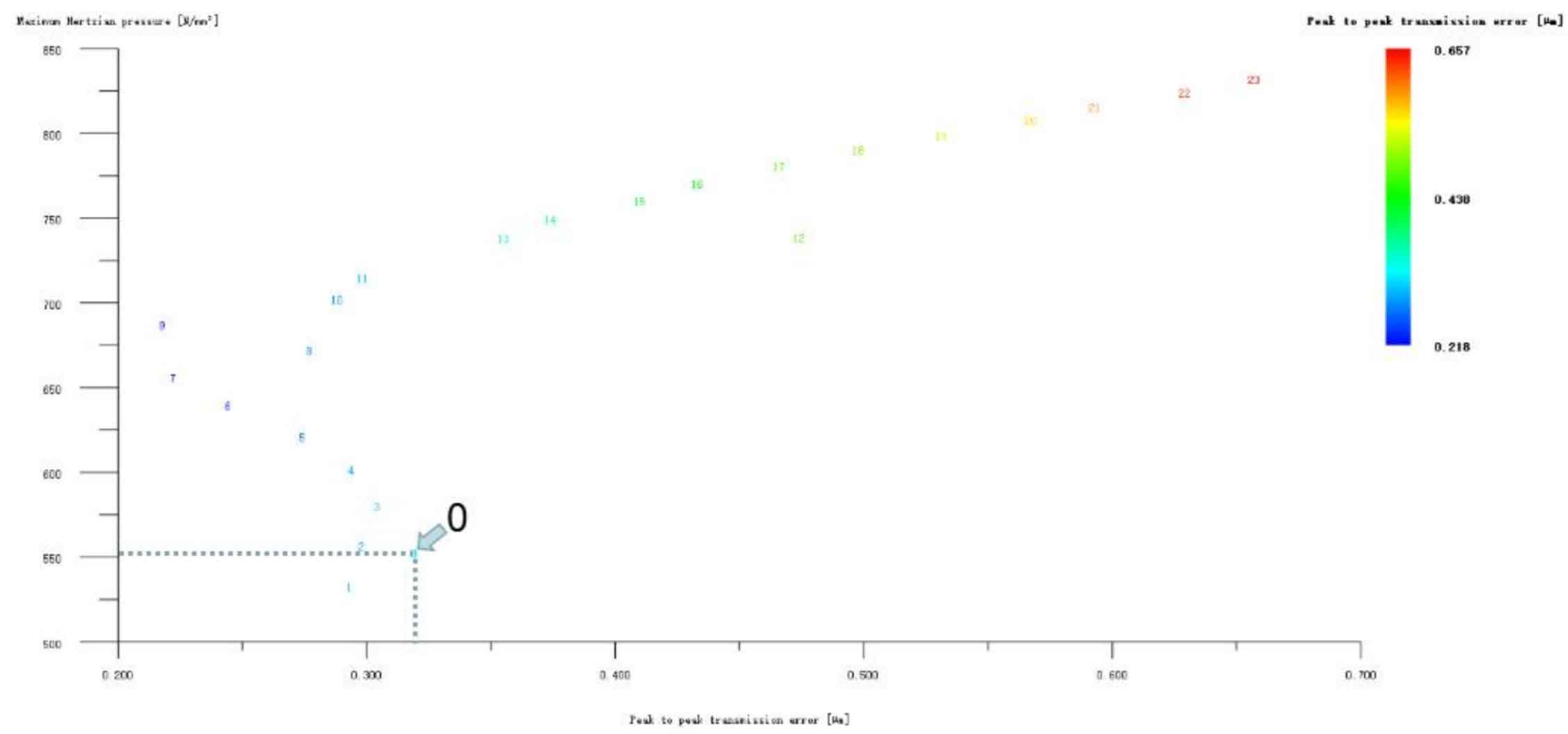
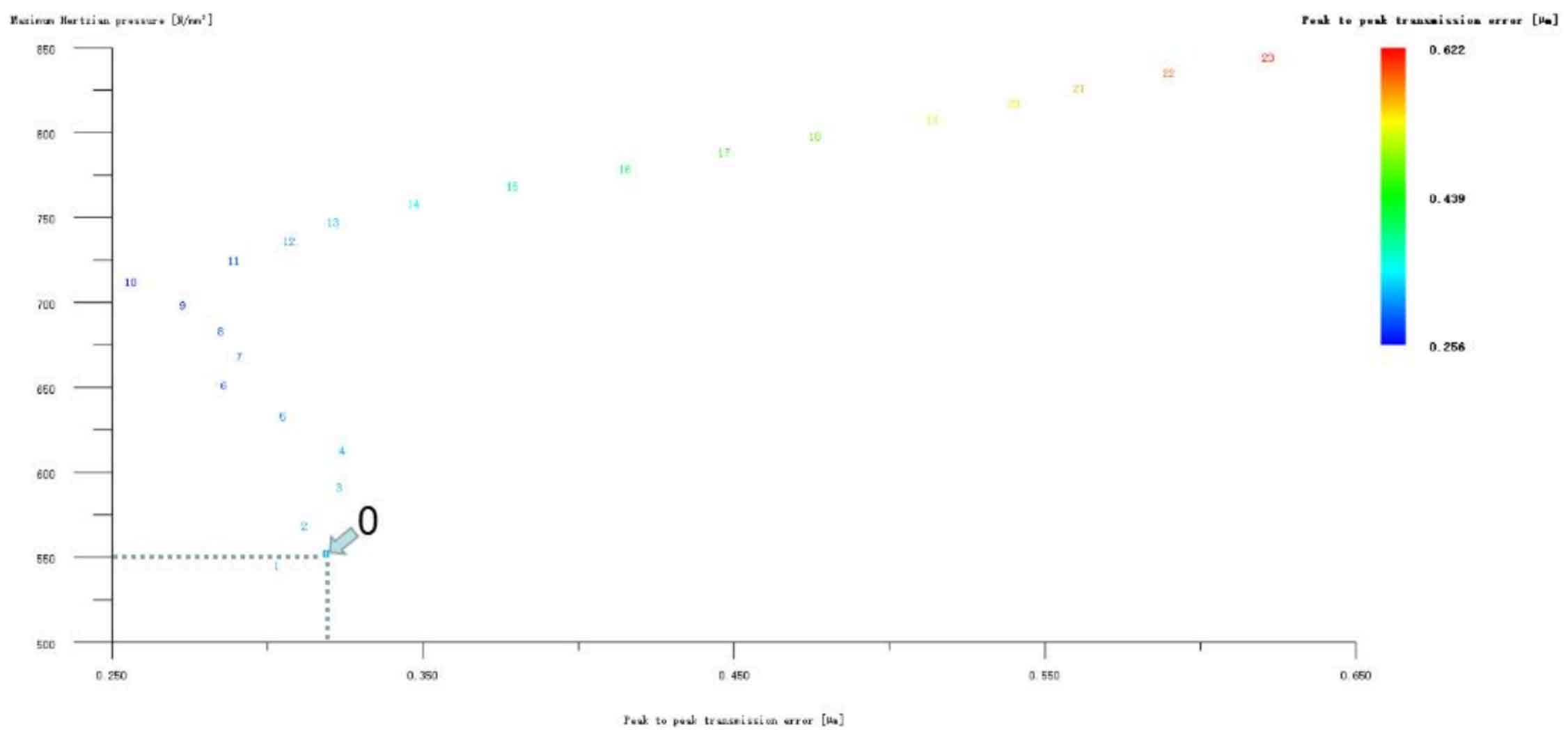
Figure 11 (a), Figure 11 (b), Figure 11 (c), Figure 11 (d) and Figure 11 (e) respectively show the drum modification of the pinion tooth profile, the drum modification of the big gear tooth profile, the compound modification of the big gear long tooth profile top arc plus the drum modification, the compound modification of the big gear long tooth profile top involute plus the drum modification, and the compound modification of the big gear long tooth profile top broken arc plus the drum modification. Obviously, Scheme 1 in Figure 11 (a), Scheme 1 in Figure 11 (b), Scheme 1 in Figure 11 (c), Scheme 1 in Figure 11 (d) and Scheme 1 in Figure 11 (e) are the best schemes for each composite modification method. In order to facilitate analysis, these optimal schemes are arranged into No. 1, No. 2, No. 3, No. 4 and No. 5 in sequence, where No. 0 represents unreformed, and the meshing performance of the front and rear parts of the composite modification of each scheme is shown in Fig. 12 and 13. It can be seen from Figure 12 that after the optimization and modification of the tooth crest arc, involute and polyline arc of the large tooth profile of the helical gear pair, the compound modification of the tooth drum (No. 3, 4 and 5 schemes) can significantly reduce the transmission error, thus achieving the goal of optimizing the transmission error and contact stress of the helical gear pair. However, according to Figure 13, if the tooth profile of a gear of the helical gear pair is drum modified, it is not worthwhile to consider the tooth drum compound modification (No. 1 and No. 2 schemes), because its transmission error and Hertz contact stress are significantly higher than before the compound modification. Therefore, No. 3, No. 4 and No. 5 can be used as the composite modification optimization scheme, and their detailed modification parameters and performance.