
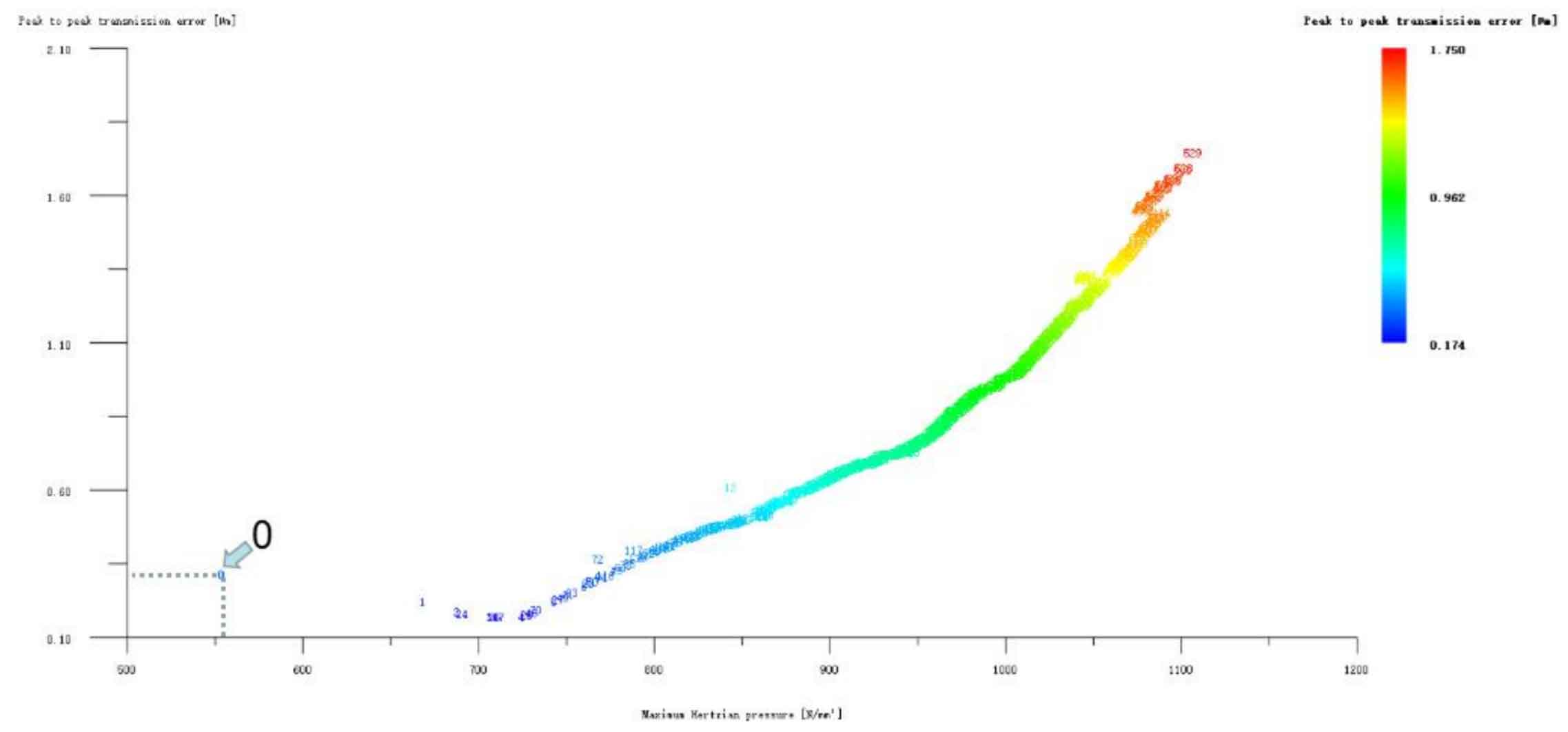
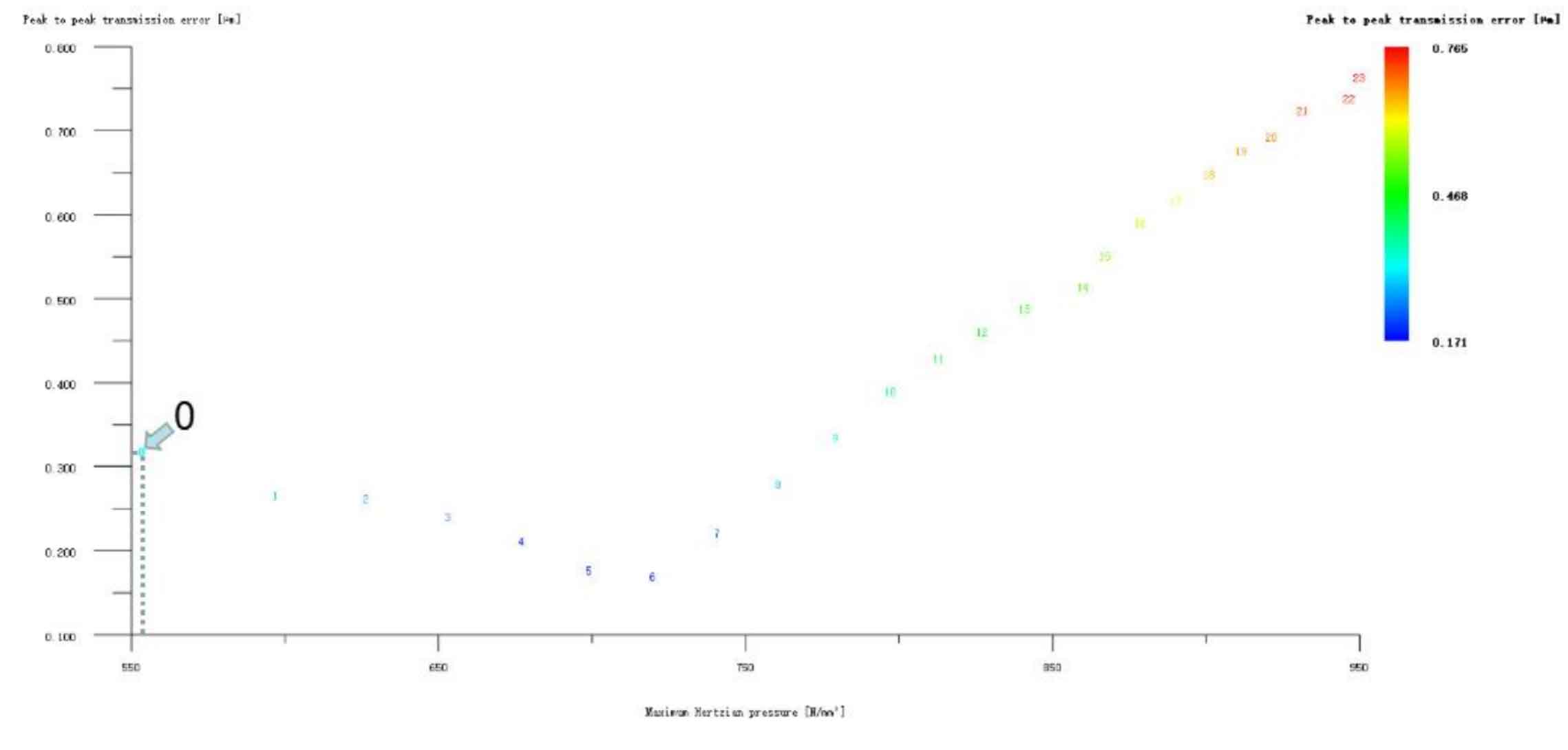
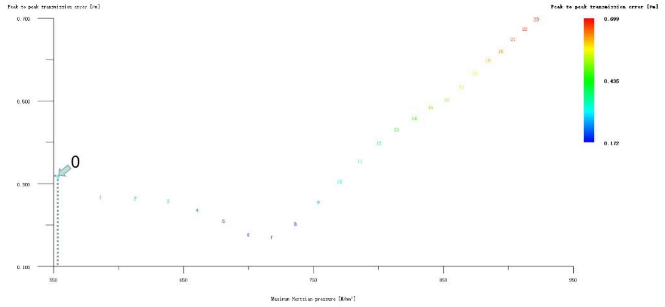
Figures 1, 2 and 3 show the drum shape modification of the big and small gears at the same time, the drum shape modification of the small gear teeth only, and the drum shape modification of the big gear teeth only. The ordinates in all drawings represent the transmission error, and the unit is μ m; The abscissa represents Hertz contact stress, in N/mm2. It can be seen from the analysis of the three figures that although the tooth drum modification method has no special requirements for the selection of large and small modified helical gears, and there are optimization schemes that can reduce the transmission error of the helical gear pair, which is inconsistent with the conclusion mentioned above that the tooth drum modification is mainly to reduce the transmission error of the helical gear pair, the Hertz contact stress in these optimization schemes has increased relative to the unmodified ones.
The idea of profile modification is based on the optimization scheme of tooth profile modification and then consider the tooth profile compound modification. If the tooth profile compound modification is inverted for the tooth profile drum modification optimization scheme with low transmission error, the two schemes are repeated. Therefore, all the tooth profile drum modification schemes are omitted here.
Of course, if only vibration reduction and noise reduction are considered in engineering practice and the strength of helical gears is not concerned, the tooth drum shape modification is the best choice. Taking the helical gear pair as an example, if only the pinion tooth is modified to the drum shape, the transmission error of the No. 6 scheme is the lowest, 0.171 μ m. 0.148 lower μ m. The reduction is 46.4%, and its modification amount is pinion 6 μ m. The big gear is not shaped.