
In the field of mechanical transmission systems, herringbone gears play a crucial role due to their high load-carrying capacity and smooth operation. As an engineer specializing in gear design, I have extensively studied the modification techniques for herringbone gears to enhance their performance. This article presents a comprehensive approach to optimizing the modification design of herringbone gears, focusing on profile and lead modifications. I will discuss the methodology, mathematical modeling, contact analysis, and optimization processes, all aimed at minimizing transmission errors and improving gear meshing characteristics. Throughout this discussion, I will emphasize the importance of herringbone gears in various applications, such as helicopter transmissions, where reliability and efficiency are paramount.
Herringbone gears, also known as double helical gears, consist of two helical gear sections with opposite helix angles, effectively canceling axial forces. This unique design reduces bearing loads and increases stability, making herringbone gears ideal for high-speed and heavy-duty applications. However, like all gears, herringbone gears are susceptible to misalignments, manufacturing errors, and deflections under load, which can lead to increased noise, vibration, and premature failure. To mitigate these issues, modification techniques, such as profile and lead crowning, are employed. In this work, I propose a novel three-segment profile modification method for the pinion, combined with lead modification, to optimize the meshing behavior of herringbone gears.
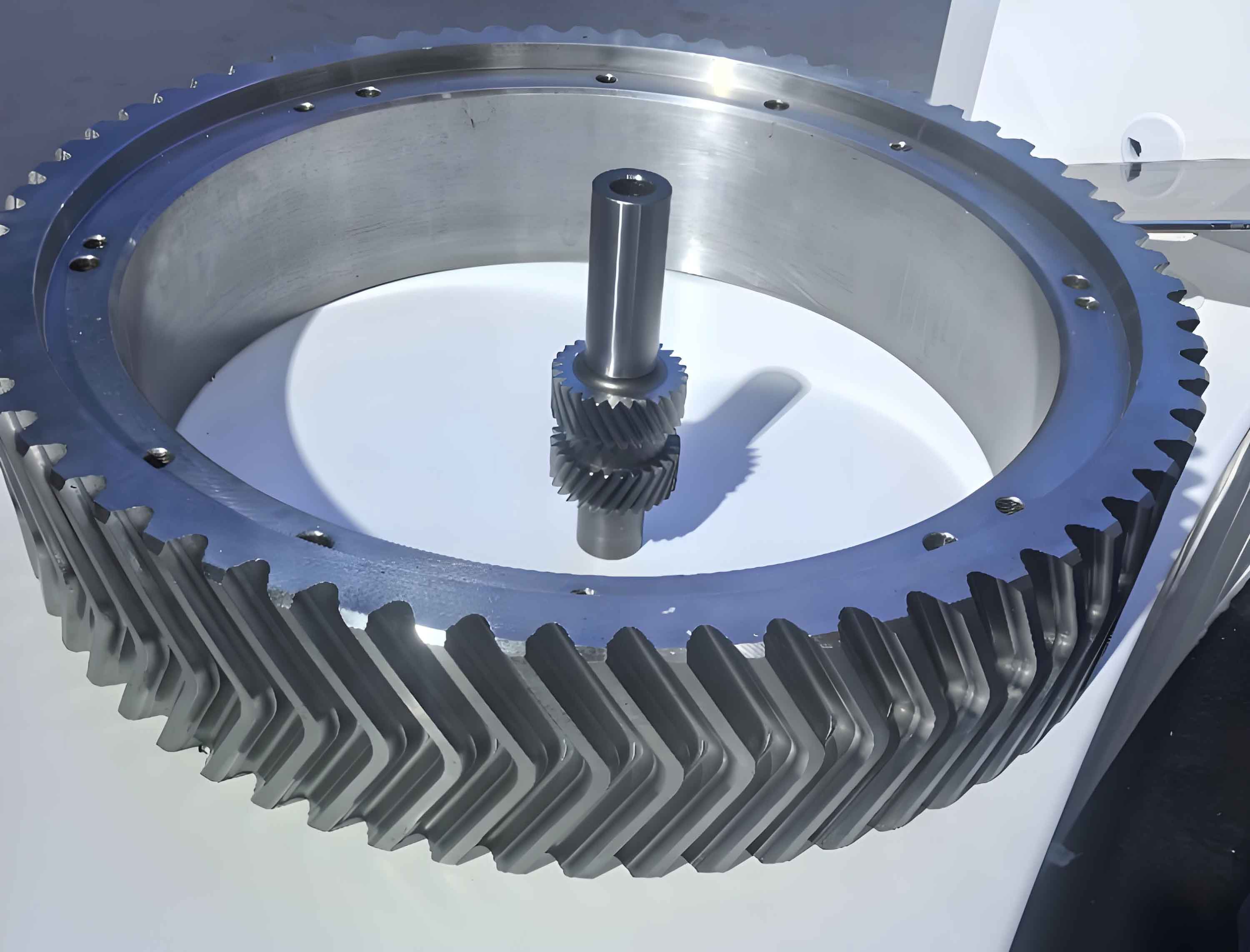
The core of my approach lies in modifying the cutting tool geometry to achieve the desired gear tooth surface. Traditionally, profile modification involves altering the tool’s cutting edge to create a non-linear tooth profile. For herringbone gears, I implement a three-segment parabolic modification on the pinion profile, replacing the straight rack profile with three connected parabolic curves. This method allows for precise control over the tooth form, enabling optimized contact patterns and reduced stress concentrations. The tool surface equation is derived based on this modified geometry, which I will elaborate on in the following sections.
To analyze the meshing behavior of herringbone gears, I establish a coordinate system that accounts for the dual helical sections. This system facilitates tooth contact analysis (TCA) and loaded tooth contact analysis (LTCA), which are essential for evaluating transmission errors and load distribution. By integrating these analyses, I can simulate the gear pair’s performance under various operating conditions, including misalignments and torque loads. The goal is to minimize the loaded transmission error (LTE), which directly impacts noise and vibration levels. Optimization is performed using the complex method, a direct search algorithm, to find the best modification parameters. Through case studies, I demonstrate that even without considering installation errors, optimized modifications significantly reduce the sensitivity of herringbone gears to axis misalignments.
In this article, I will first detail the three-segment profile modification method, including the mathematical formulation of the tool surface. Then, I will describe the coordinate systems for herringbone gear meshing and the procedures for TCA and LTCA. Next, I will present the optimization framework and results from a practical example. Finally, I will explain how to calculate the pinion profile modification quantities for manufacturing purposes. Throughout, I will use tables and equations to summarize key points, ensuring clarity and depth. The repeated mention of herringbone gears underscores their significance in modern engineering applications.
Three-Segment Profile Modification for Herringbone Gears
Profile modification is a common technique to improve gear meshing by altering the tooth flank geometry. For herringbone gears, I focus on modifying the pinion profile using a three-segment parabolic curve. This approach involves replacing the linear profile of a rack cutter with three parabolic segments, as shown in the tool normal profile. The equations for these segments in the tool coordinate system are as follows:
$$y_1 = a_1 u^2$$
$$y_2 = a_2 u^2 + b_2 u + c_2$$
$$y_3 = a_3 u^2 + b_3 u + c_3$$
Here, \(u\) is the distance from the parabola vertex along the tooth profile, and \(y_1, y_2, y_3\) represent the parabolic curves for different segments. The coefficients \(a_i, b_i, c_i\) are determined based on continuity and smoothness constraints at the junction points, as well as specified modification amounts \(d_1, d_2, d_3\). The constraints include:
- Continuity at junction points: \(y_1(u_1) = y_2(u_1)\) and \(y_2(u_2) = y_3(u_2)\).
- Smoothness at junction points: \(y_1′(u_1) = y_2′(u_1)\) and \(y_2′(u_2) = y_3′(u_2)\).
- Maximum modification amounts: \(y_1(u_i) = d_1\), \(y_2(u_0) = d_2\), and \(y_3(u_3) = d_3\), where \(u_i, u_0, u_3\) are defined based on the working profile length.
By solving these constraints, the coefficients can be uniquely determined. The tool surface equation is then derived through coordinate transformation from the tool profile to the tool surface. In the tool coordinate system \(o_c x_c y_c\), the surface equation for each segment is:
$$\mathbf{r}_c = \begin{bmatrix}
-y_i \sin\alpha + (u – d_p) \cos\alpha \\
y_i \cos\alpha \cos\beta + l \sin\beta + [(u – d_p) \sin\alpha + a_m] \cos\beta \\
-y_i \cos\alpha \sin\beta + l \cos\beta – [(u – d_p) \sin\alpha + a_m] \sin\beta
\end{bmatrix}$$
where \(i = 1, 2, 3\); \(l\) is the parameter along the tool length; \(\alpha\) is the pressure angle; \(\beta\) is the helix angle; \(d_p\) is the vertex position parameter; and \(a_m\) is the normal half-tooth thickness on the tool pitch line. This equation allows for generating the modified pinion tooth surface when machining herringbone gears. The junction points \(u_1\) and \(u_2\) control the transition between segments, enabling tailored modifications for different regions of the tooth profile.
For herringbone gears, the left and right helical sections can be machined with different modification tools to account for asymmetric loading or manufacturing considerations. This flexibility enhances the optimization potential for herringbone gears in complex applications.
Coordinate System and Contact Analysis for Herringbone Gears
To analyze the meshing of herringbone gears, I establish a comprehensive coordinate system that accommodates both helical sections. The system includes fixed coordinate systems attached to the pinion and gear for each section, as well as auxiliary systems to account for installation errors such as axis misalignments and axial displacements. The key coordinate systems are:
- \(S_{h1}\) and \(S_{k1}\): Fixed systems at the midpoints of the pinion tooth width for the two helical sections, with Z-axes aligned with the pinion rotation axis.
- \(S_{h2}\) and \(S_{k2}\): Fixed systems for the gear in ideal alignment, parallel to \(S_{h1}\) and \(S_{k1}\).
- \(S’_{h2}\) and \(S’_{k2}\): Auxiliary systems that incorporate installation errors, including linear displacements \(\Delta X, \Delta Y, \Delta Z\) and angular misalignment \(\Delta \gamma\).
The transformation between these systems allows for simulating real-world conditions. For tooth contact analysis (TCA), I solve the equations of meshing for both helical sections simultaneously. The basic TCA equations ensure contact continuity and common normals at the point of contact. For a pair of mating surfaces \(\mathbf{r}_1\) and \(\mathbf{r}_2\), the conditions are:
$$\mathbf{r}_1(\theta_1, \phi_1) = \mathbf{r}_2(\theta_2, \phi_2)$$
$$\mathbf{n}_1(\theta_1, \phi_1) = \mathbf{n}_2(\theta_2, \phi_2)$$
where \(\theta_i\) and \(\phi_i\) are surface parameters, and \(\mathbf{n}_i\) are unit normals. By applying these conditions to the modified tooth surfaces of herringbone gears, I can compute the geometric transmission error (GTE) and tooth surface separation for discrete points. The transmission error is defined as the deviation from ideal motion, given by:
$$\Delta \phi_2 = \phi_2 – \frac{N_1}{N_2} \phi_1$$
where \(N_1\) and \(N_2\) are tooth numbers, and \(\phi_1, \phi_2\) are rotation angles. For herringbone gears, the GTE is evaluated for both helical sections, and the overall error is a combination that accounts for phase differences.
Loaded tooth contact analysis (LTCA) extends TCA by including elastic deformations under load. I use a numerical method where the tooth contact is discretized into patches, and compatibility equations are solved to determine load distribution. The constraints for herringbone gears include:
- The sum of discrete loads on all contact patches for both helical sections equals the applied torque.
- The axial force components from the left and right sections are equal, ensuring force balance in herringbone gears.
The LTCA equations can be formulated as a linear complementarity problem. For each contact patch \(j\), the deformation \(\delta_j\) is related to the load \(F_j\) via flexibility coefficients \(a_{jk}\):
$$\delta_j = \sum_{k} a_{jk} F_k + \delta_{0j}$$
where \(\delta_{0j}\) is the initial separation from TCA. The contact condition requires \(\delta_j \geq 0\) and \(F_j \geq 0\), with \(\delta_j F_j = 0\). Solving this system yields the load distribution and loaded transmission error (LTE), which is critical for assessing performance. By analyzing a full meshing cycle, I obtain the LTE curve for herringbone gears under various torque levels.
Optimization of Modification Parameters
The optimization goal is to minimize the loaded transmission error of herringbone gears, thereby reducing noise and improving durability. I use the complex method, a direct search optimization technique suitable for constrained nonlinear problems. The design variables include:
- Profile modification parameters: Maximum modification amounts \(d_1, d_2, d_3\) and junction positions \(u_1, u_2\) for the three-segment parabola on the tool.
- Lead modification parameters: Coefficients \(a, b, c\) for a parabolic lead crowning along the helix direction, expressed as \(y = a x^2 + b x + c\) in the normal direction.
For simplicity, in symmetric herringbone gears, the same modification can be applied to both helical sections, but asymmetric optimization is possible if needed. The objective function \(f\) is defined as the peak-to-peak value of LTE over one mesh cycle:
$$f = \max(\Delta \phi_2) – \min(\Delta \phi_2)$$
Constraints include bounds on modification amounts to ensure manufacturability and positive contact ratios. The complex method iteratively updates a set of points (complex) in the design space, moving towards the optimum while satisfying constraints. The algorithm steps are:
- Initialize a complex of \(n+1\) points for \(n\) variables, ensuring feasibility.
- Evaluate the objective function at each point.
- Replace the worst point with a new point reflected towards the centroid of the better points.
- Repeat until convergence criteria are met, such as small changes in objective function or maximum iterations.
This approach efficiently handles the multi-variable optimization for herringbone gears, yielding optimal modification parameters that minimize LTE even under misalignments.
Case Study: Optimization Results for Herringbone Gears
To demonstrate the method, I apply it to a herringbone gear pair with parameters listed in Table 1. The gears are designed for a helicopter transmission, with an input torque of 4000 N·m. The optimization focuses on profile and lead modifications, assuming symmetric modifications for both helical sections initially.
| Parameter | Pinion | Gear |
|---|---|---|
| Number of teeth, \(z\) | 34 | 143 |
| Normal module, \(m_n\) (mm) | 4.5 | |
| Normal pressure angle, \(\alpha_n\) (degrees) | 20 | |
| Helix angle, \(\beta\) (degrees) | 34.29 | |
| Face width, \(B\) (mm) | 90 × 2 | 90 × 2 |
| Hand of helix | Right-left | Left-right |
| Gap width, \(W\) (mm) | 70 | |
For profile modification, I assume the parabolic segments occupy equal heights along the tooth profile: \(h/4, h/2, h/4\), where \(h\) is the working profile height on the tool. This reduces the variables to \(d_2\) and \(d_3\) (with \(d_1 = 0\) for no modification at the tip). Lead modification is simplified to a quadratic term \(a\), with \(b = c = 0\). The optimized parameters after applying the complex method are shown in Table 2.
| Parameter | Value |
|---|---|
| \(d_2\) (mm) | 0.003 |
| \(d_3\) (mm) | 0.002 |
| \(a\) (×10⁻⁹) | -2.5 |
The loaded transmission error was computed for torque levels of 3500 N·m, 4000 N·m, and 4500 N·m. Without optimization, the LTE peak-to-peak value at 4000 N·m was 0.382 arcminutes. After optimization, it reduced to 0.2 arcminutes, indicating a significant improvement. The LTE curves for both cases are plotted in Figure 1, showing smoother variations with optimization.
To test robustness, I introduced an axis misalignment error \(\Delta \gamma = 0.1\) arcminutes in the \(Y_{h1}-Z_{h1}\) plane. Using the same optimized parameters, the LTE was recalculated and compared to the unoptimized case with misalignment. The results, shown in Figure 2, demonstrate that optimized herringbone gears maintain lower LTE despite misalignments, highlighting the effectiveness of the modification design. This underscores the value of optimization in enhancing the tolerance of herringbone gears to installation errors.
Calculation of Pinion Profile Modification Quantities
For manufacturing, it is essential to translate the tool-based modification into actual gear tooth geometry. I provide a method to calculate the pinion profile modification quantities, regardless of the machining process. The standard involute profile for a helical gear in the transverse plane can be derived from basic gear geometry. For a modified pinion, the profile is obtained by transforming the tool surface equation to the gear coordinate system.
Let \((X_{h1}, Y_{h1})\) be the coordinates of the standard involute profile in the transverse plane. The modified profile \((X_h, Y_h)\) is derived from the tool surface equation through coordinate transformations involving rotation and translation. The modification amount \(\Delta L\) along the tooth profile direction is calculated as:
$$\Delta L = X_h – X_{h1}$$
This is evaluated at a series of points along the tooth height \(Y = \{Y_1, Y_2, \dots, Y_n\}\). To relate this to the line of action, I use the generating line formula:
$$Y_k = \sqrt{Y^2 – r_{b1}^2}$$
where \(r_{b1}\) is the pinion base radius, \(Y\) is the radial distance on the tooth profile, and \(Y_k\) is the corresponding length along the line of action. The modification amount at \(Y_k\) equals that at \(Y\), allowing for mapping onto the contact path.
For the case study, the calculated modification amounts for the pinion are summarized in Table 3 and plotted in Figure 3. The profile modification shows a three-segment pattern, while the lead modification is minimal. In practice, for herringbone gears, if lead modification is negligible, profile modification alone may suffice for simplicity, as seen in this example where LTE improvements were primarily due to profile changes.
| Tooth Height Position (mm) | Profile Modification \(\Delta L\) (mm) | Lead Modification (Normal, mm) |
|---|---|---|
| 0 (Root start) | 0.002 | Parabolic with \(a = -2.5 \times 10^{-9}\) |
| 2.5 | 0.0015 | |
| 5.0 (Mid) | 0.003 | |
| 7.5 | 0.0015 | |
| 10.0 (Tip end) | 0.002 |
This calculation method ensures that any manufacturing process, whether hobbing, grinding, or shaping, can achieve the desired modification by targeting these quantities. For herringbone gears, this precision is crucial for maintaining balanced loading across both helical sections.
Discussion and Implications for Herringbone Gears
The optimization of modification design for herringbone gears has far-reaching implications in industries such as aerospace, marine, and heavy machinery. By minimizing transmission errors, we can achieve quieter and more efficient gear systems. The three-segment profile modification offers a flexible way to tailor tooth contact, while lead modification addresses axial variations. The combined approach allows herringbone gears to perform reliably under misalignments and dynamic loads.
In practice, the optimization process should consider specific application constraints, such as torque fluctuations, temperature effects, and lubrication conditions. For herringbone gears, the interaction between left and right helical sections adds complexity, but also provides opportunities for advanced designs. Future work could explore asymmetric modifications to further optimize performance for non-uniform loading scenarios.
Moreover, the use of advanced materials and manufacturing technologies, like additive manufacturing, could integrate these modification geometries directly into herringbone gear designs, pushing the boundaries of performance. The methodology presented here serves as a foundation for such innovations, emphasizing the importance of systematic analysis and optimization in gear engineering.
Conclusion
In this article, I have presented a comprehensive framework for optimizing the modification design of herringbone gears. The three-segment profile modification method, combined with lead crowning, effectively reduces loaded transmission errors and enhances misalignment tolerance. Through detailed mathematical modeling, contact analysis, and optimization using the complex method, I demonstrated significant improvements in a case study. The calculation of pinion modification quantities provides a practical guide for manufacturing. Herringbone gears, with their unique double helical structure, benefit greatly from such tailored modifications, ensuring high performance in demanding applications. As technology advances, continued refinement of these techniques will further solidify the role of herringbone gears in modern mechanical systems.
The integration of tables, equations, and visual elements in this discussion underscores the technical depth required for herringbone gear design. I hope this work inspires further research and application in the field, driving innovation towards quieter, more durable, and efficient gear transmissions. The repeated focus on herringbone gears throughout this article highlights their critical importance, and I am confident that optimized modification strategies will continue to unlock their full potential in engineering solutions worldwide.