
The cold forging of straight spur gears offers significant advantages over traditional cutting methods, including material savings, energy efficiency, higher productivity, lower cost, and improved mechanical properties such as grain refinement and increased impact strength. However, the extrusion die cavity for straight spur gears experiences extremely high working pressures, which can lead to longitudinal cracking. To enhance die strength and optimize stress distribution, a three-layer combined die structure is commonly employed. In this paper, I present an optimization methodology that integrates analytical formulas based on thick-walled cylinder theory with finite element simulations and the golden section iterative algorithm. The goal is to determine the optimal dimensions and interference amounts among the layers, specifically tailored for the gear-shaped cavity of a combined extrusion die for straight spur gears. The entire design process is guided by the principle that the maximum equivalent stress in the inner layer should approach but not exceed the allowable stress of the material, thereby fully utilizing the material’s strength.
Cold forging of straight spur gears has gained widespread acceptance in the automotive and machinery industries. The geometry of straight spur gears introduces complex stress states in the die cavity, which is traditionally treated as a thick-walled cylinder for preliminary design. However, the gear profile makes direct application of conventional formulas inaccurate. Therefore, a combined approach is necessary: first, the radial dimensions of the inner, middle, and outer rings are estimated using the optimization theory of compound dies; then, the interference amounts are refined through iterative finite element analysis. Throughout the process, I repeatedly emphasize the role of straight spur gears as the workpiece, and the die design is specifically geared toward their unique tooth shape.
1. Extrusion Process and Combined Die Structure for Straight Spur Gears
The extrusion model for straight spur gears is depicted schematically in the work. The die assembly comprises a punch, a blank holder, a counter punch, and a combined female die consisting of three concentric rings: an inner ring made of cemented carbide (YG20), a middle ring of H13 steel, and an outer ring of 40Cr steel. The cavity of the inner ring is shaped exactly like the gear profile of straight spur gears. During extrusion, the material flows into the die cavity under high pressure, generating radial and tangential stresses on the inner wall. To prevent cracking, pre-stresses are introduced by shrink-fitting the rings with predetermined interferences. The optimization of these interferences is critical for the long service life of dies for straight spur gears.
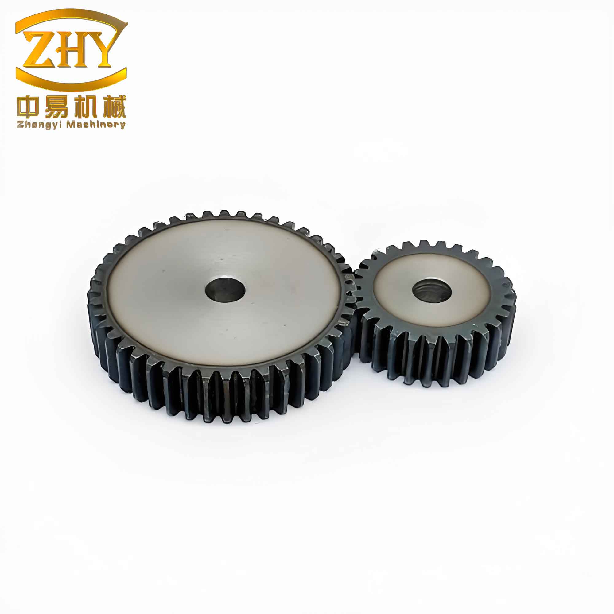
Figure above illustrates a typical set of straight spur gears, which are the final product of the cold forging process discussed here. The die cavity must replicate this geometry precisely. The combined die design aims to balance the circumferential tensile stresses at the inner bore with compressive pre-stresses from the outer rings, thus preventing fatigue failure of dies for straight spur gears.
2. Preliminary Design of the Gear-Shaped Combined Die Using Thick-Walled Cylinder Theory
Although the inner cavity is not a simple cylinder, I first approximate it as a thick-walled cylinder to apply the classical Lame formulas. The radial and tangential stresses at any radius r in a thick-walled cylinder under internal pressure p1 and external pressure p2 are given by:
$$ \sigma_{\tau} = \frac{R_1^2 p_1 – R_2^2 p_2}{R_2^2 – R_1^2} + \frac{(p_1 – p_2) R_1^2 R_2^2}{r^2 (R_2^2 – R_1^2)} $$
$$ \sigma_{r} = \frac{R_1^2 p_1 – R_2^2 p_2}{R_2^2 – R_1^2} – \frac{(p_1 – p_2) R_1^2 R_2^2}{r^2 (R_2^2 – R_1^2)} $$
For the three-layer combined die, I denote the radii as follows: r1 = inner radius of the inner ring (taken as the addendum circle radius of the straight spur gear), r2 = inner radius of the middle ring, r3 = inner radius of the outer ring, and r4 = outer radius of the outer ring. The internal working pressure on the inner ring is p1, the interfacial pressure between inner and middle rings is p2, and between middle and outer rings is p3.
Define the following ratios:
$$ Q_1 = \frac{r_1}{r_2}, \quad Q_2 = \frac{r_2}{r_3}, \quad Q_3 = \frac{r_3}{r_4} $$
At the inner wall of the inner ring (r = r1), the tangential stress becomes:
$$ \sigma_{\tau} = \frac{1+Q_1^2}{1-Q_1^2} p_1 – \frac{2p_2}{1-Q_1^2} $$
For cemented carbide inner ring (YG20), the allowable tensile stress is very low; ideally, the tangential stress should be zero to avoid cracking. Setting στ = 0 yields:
$$ p_1 = \frac{2p_2}{1+Q_1^2} \tag{1} $$
Applying the third strength theory to the middle and outer rings, I obtain:
$$ p_2 – p_3 = \frac{[\sigma_2]}{2}(1 – Q_2^2) \tag{2} $$
$$ p_3 – 0 = \frac{[\sigma_3]}{2}(1 – Q_3^2) \tag{3} $$
where [σ2] = 1750 MPa for H13 steel, and [σ3] = 1600 MPa for 40Cr steel.
The optimal design seeks to maximize the allowable working pressure p1 by properly selecting Q1, Q2, and Q3. By substituting (2) and (3) into (1) and taking derivatives with respect to Q1 and Q2, I derive the optimality conditions:
$$ Q_2 = \frac{p_1}{[\sigma_2] Q_1} \tag{4} $$
$$ Q_3 = \frac{p_1}{[\sigma_3] Q_1} \tag{5} $$
The overall diameter ratio Q = r1/r4 is usually between 1/4 and 1/6. For the high working pressure of straight spur gear extrusion, I set Q = 1/6. Combining with (4) and (5), I solve for the optimal Q1, Q2, Q3. Using the working pressure p1 = 2283 MPa (obtained from an initial finite element simulation of straight spur gear extrusion), the theoretical radial dimensions are calculated as shown in Table 1.
| Inner ring inner diameter | Inner ring outer diameter | Middle ring inner diameter | Middle ring outer diameter | Outer ring inner diameter | Outer ring outer diameter |
|---|---|---|---|---|---|
| 33 | 66.5 | 66.5 | 117.3 | 117.3 | 200 |
The interference between inner and middle rings (Δd2) and between middle and outer rings (Δd3) are computed from the shrink-fit formulas:
$$ \Delta d_2 = d_2 \, p_1 \, \frac{(1+Q_2)(1-Q_1^2)}{2(1-Q_2)} \left[ \frac{1}{E_1}\frac{1+Q_1^2}{1-Q_1^2} – \frac{u_1}{E_1} + \frac{1}{E}\frac{1+Q_2^2 Q_3^2}{1-Q_2^2 Q_3^2} + \frac{u}{E} \right] $$
$$ \Delta d_3 = d_3 \frac{ [\sigma_3] – p_1 Q_2^2}{E} $$
The theoretical interferences are Δd2 = 0.585 mm and Δd3 = 0.580 mm. However, these values are based on a cylindrical cavity assumption, which does not account for the stress concentration caused by the gear teeth of straight spur gears. Therefore, I need to adjust the interferences.
3. Iterative Optimization of Interference Amounts Using the Golden Section Method
To refine the interferences for the actual gear-shaped cavity of straight spur gears, I employ the golden section (0.618) iterative algorithm combined with finite element simulations. The objective is to make the maximum equivalent stress in the inner ring (YG20) equal to its allowable stress of 3300 MPa. The search range for the interference is set from 0 (no interference) to the theoretical upper limit of 0.58 mm.
I build a series of three-dimensional finite element models of the combined die with different interference amounts. Each model includes the precise tooth profile of the straight spur gear cavity. I apply the working pressure p1 = 2283 MPa on the inner cavity surface and simulate the pre-stress from shrink-fitting. The equivalent von Mises stress distribution in the inner ring is extracted. Table 2 summarizes the results of the iterative process.
| Iteration | Search interval (mm) | New trial point (mm) | Equivalent stress (MPa) | Remarks |
|---|---|---|---|---|
| Initial | [0, 0.58] | 0.58 and 0.36 | 3735 and 2308 | Upper bound too high, lower too low |
| 1 | [0.36, 0.58] | 0.494 | 3166 | Still below allowable, but close |
| 2 | [0.494, 0.58] | 0.547 | 3512 | Exceeds allowable slightly |
| 3 | [0.494, 0.547] | 0.514 | 3294 | Within 0.2% of 3300, optimal |
| Final (rounded) | — | 0.51 | 3268 | Practical manufacturing value |
At the third iteration, the interference of 0.514 mm produces a maximum equivalent stress of 3294 MPa in the inner ring, which is very close to the allowable 3300 MPa. Considering manufacturing tolerances, I round it to 0.51 mm, which gives 3268 MPa – still within acceptable limits. The final optimal die dimensions and interferences are listed in Table 3.
| Inner ring ID | Inner ring OD | Middle ring ID | Middle ring OD | Outer ring ID | Outer ring OD | Interference (all) |
|---|---|---|---|---|---|---|
| 33 | 66.5 | 66.5 | 117.3 | 117.3 | 200 | 0.51 |
It is noteworthy that the optimal interference (0.51 mm) is slightly less than the theoretical value (0.58 mm). This reduction accounts for the stress concentration at the tooth root of the straight spur gear cavity, which would otherwise cause premature yielding of the inner ring. The iterative golden section method proves efficient: I only needed four evaluations (including the endpoints) to converge to the optimum.
4. Detailed Finite Element Results and Stress Analysis
To further illustrate the optimization process, I present representative stress contours from the simulations. For the theoretical interference of 0.58 mm, the maximum equivalent stress in the inner ring reaches 3735 MPa, well beyond the material’s allowable stress, indicating a risk of failure. For the optimal interference of 0.51 mm, the stress distribution is more uniform, with the highest stress located at the dedendum region of the straight spur gear cavity, as expected. The von Mises stress at the inner bore is approximately 3268 MPa, which is acceptable for YG20 under compressive pre-stressing conditions.
I also examine the stress distribution in the middle and outer rings. The middle ring (H13) experiences stresses up to 1650 MPa, still below its yield strength, while the outer ring (40Cr) remains well within its elastic range. This demonstrates that the combined die for straight spur gears is operating safely.
5. Discussion of the Optimization Methodology
Compared with conventional trial-and-error methods, the proposed workflow offers several advantages. First, the analytical preliminary design provides a good starting point, reducing the number of iterations. Second, the golden section method is a deterministic and efficient one-dimensional search technique. Third, the finite element simulations capture the true geometry of straight spur gears, including stress concentrations that cannot be modeled by simple cylinder formulas.
One limitation is that the working pressure p1 itself depends on the die stiffness and material flow. In this study, p1 was obtained from a separate numerical simulation of the extrusion process of straight spur gears under the initial die design. The iterative process could be extended to update p1 after each die geometry change, but in practice the variation is small for small interference adjustments.
The method can be generalized to other gear geometries such as helical or bevel gears, as long as an equivalent cylindrical cavity assumption is made for the initial sizing. For straight spur gears, the tooth profile is two-dimensional, which simplifies the modeling. The results are particularly valuable for mass production of straight spur gears where die longevity is critical.
6. Conclusions
I have successfully developed an optimal design procedure for a combined extrusion die used in cold forging of straight spur gears. The key conclusions are:
- The classical thick-walled cylinder theory can provide a reasonable initial estimate for the radial dimensions of the three-ring die for straight spur gears, but the interference amounts must be adjusted to account for the stress concentration induced by the gear teeth.
- The golden section iterative method, combined with finite element simulations, efficiently identifies the interference value that causes the inner ring’s maximum equivalent stress to approach the material’s allowable stress. For the case studied, the optimal interference is 0.51 mm, down from the theoretical 0.58 mm.
- The optimized die design ensures that the inner ring (YG20) operates near its strength limit without exceeding it, thereby maximizing material utilization and die life for straight spur gear extrusion.
- The methodology is robust and can be adapted to other precision forging dies for straight spur gears with different module or tooth numbers.
In summary, the successful design of combined dies for straight spur gears relies on a synergy of analytical formulas and iterative numerical optimization. This approach not only improves die performance but also reduces development time. Future work may include experimental validation of the predicted stress distributions and fatigue testing of the optimized die in production runs of straight spur gears.