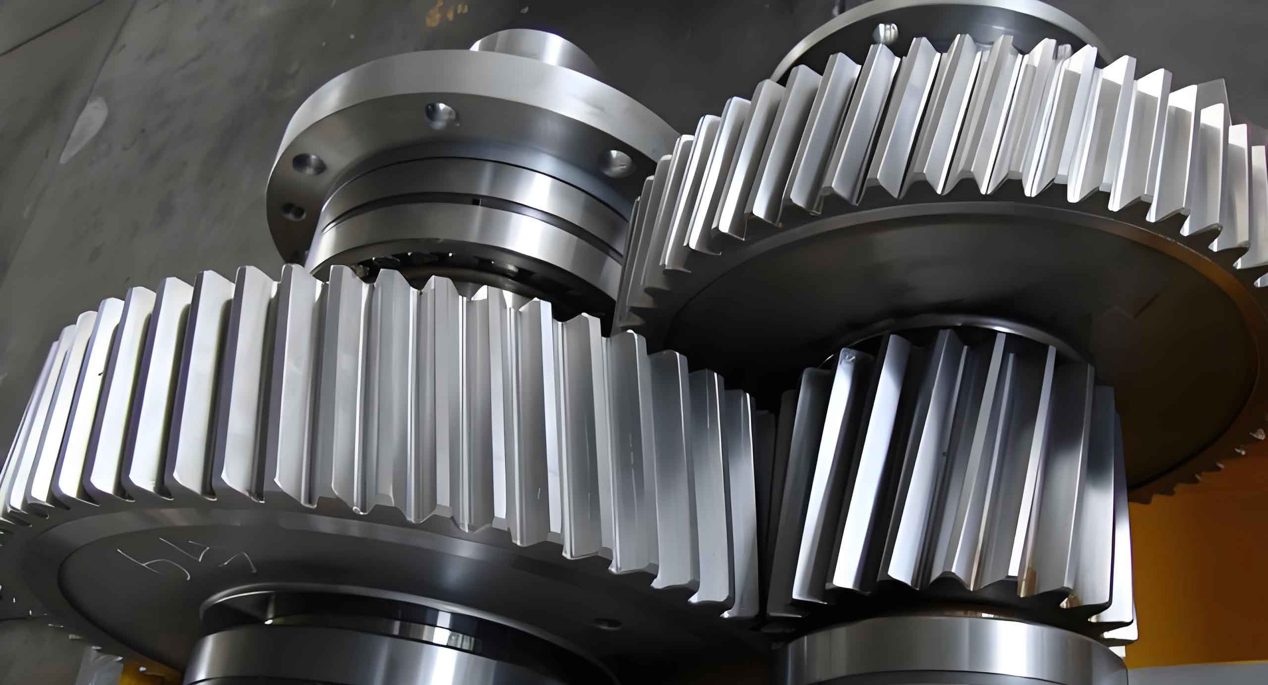
In modern automotive electric power steering (EPS) systems, the helical gear worm transmission mechanism with nylon helical gears and steel worms has gained prominence due to its low noise, cost-effectiveness, and smooth operation. However, traditional design methodologies for metal worm gears are inadequate for this material combination. This study proposes an optimized design framework integrating theoretical analysis, parametric optimization, and finite element verification.

1. Theoretical Basis for Helical Gear Worm Design
The bending stress calculation for nylon helical gears follows:
$$ \sigma_F = \frac{K F_t Y_{Fa} Y_{Sa} Y_\beta}{b m_n \varepsilon_\alpha} $$
Where:
$K$ = Load factor
$F_t = 2T/d$ = Tangential force
$Y_{Fa}$ = Form factor
$Y_{Sa}$ = Stress correction factor
$Y_\beta$ = Helix angle factor
$b$ = Face width
$m_n$ = Normal module
$\varepsilon_\alpha$ = Transverse contact ratio
2. Modification Coefficient Determination
The critical worm tip thickness constraint governs the modification coefficient:
$$ x^* = \frac{\pi – 0.8}{4\tan\alpha} – 1 $$
For PA66 helical gears meshing with 40Cr worms, the optimal tooth thickness ratio (7:3) yields:
$$ x = \frac{\pi}{10\tan\alpha} $$
Comparative analysis shows the former equation provides better gear strength when pressure angles <15°.
| Parameter | Helical Gear | Worm |
|---|---|---|
| Module (mm) | 2 | 2 |
| Pressure Angle (°) | 13.5 | 13.5 |
| Number of Starts | – | 2 |
| Center Distance (mm) | 50 | |
3. Material Properties and Safety Factors
| Material | Elastic Modulus (GPa) | Yield Strength (MPa) | Density (kg/m³) |
|---|---|---|---|
| PA66 | 1.4 | 83 | 1,140 |
| 40Cr | 211.7 | 785 | 7,850 |
4. Optimization Results
Kisssoft analysis reveals significant improvements through profile modification:
| Configuration | Gear SF | Worm SF |
|---|---|---|
| Standard | 1.60 | 10.70 |
| Modified (x=1.3086) | 2.43 | 5.35 |
| Modified (x=1.4383) | 2.51 | 4.90 |
5. Finite Element Verification
Workbench simulations confirm stress reduction in modified helical gears:
$$ \sigma_{\text{max}} = \begin{cases}
62.24\ \text{MPa} & \text{(Standard)} \\
41.12\ \text{MPa} & \text{(x=1.3086)} \\
38.18\ \text{MPa} & \text{(x=1.4383)}
\end{cases} $$
The safety factors increase from 1.33 (standard) to 2.02-2.17 after modification, demonstrating the effectiveness of the proposed helical gear optimization method.
6. Design Guidelines
For automotive EPS applications, the helical gear worm design should follow:
- Maintain worm tip thickness ≥0.4mₙ
- Optimize tooth thickness ratio between 65%-75%
- Ensure simultaneous meshing of 2-3 tooth pairs
- Use asymmetric profile modification for noise reduction
This methodology enables 52%-57% improvement in helical gear load capacity while maintaining compact packaging requirements of modern EPS systems.
