
In the field of mechanical transmission, spiral bevel gears play a critical role in transferring power between intersecting shafts, especially in automotive and aerospace applications. Traditional design methods, such as the Gleason system, often rely on fixed parameters like radial displacement coefficients and addendum coefficients, which may not yield optimal performance. These designs typically ensure basic requirements like no undercutting and adequate tooth tip thickness, but they often result in low contact ratios and insufficient strength. To address these limitations, I explore an optimization approach for high-tooth spiral bevel gears using genetic algorithms. High-tooth spiral bevel gears leverage advanced “non-zero” displacement design and high-tooth system techniques, enabling improved performance through optimization. Previous optimization methods, such as nonlinear mathematical programming, faced challenges like low success rates and inability to handle multi-objective optimization. In contrast, genetic algorithms offer a robust alternative by simulating natural evolution processes, providing global optimization capabilities, and handling complex constraints without requiring gradient information. This article delves into the methodology, implementation, and results of optimizing spiral bevel gears for maximum contact ratio, emphasizing the use of genetic algorithms to enhance the design of spiral bevel gears.
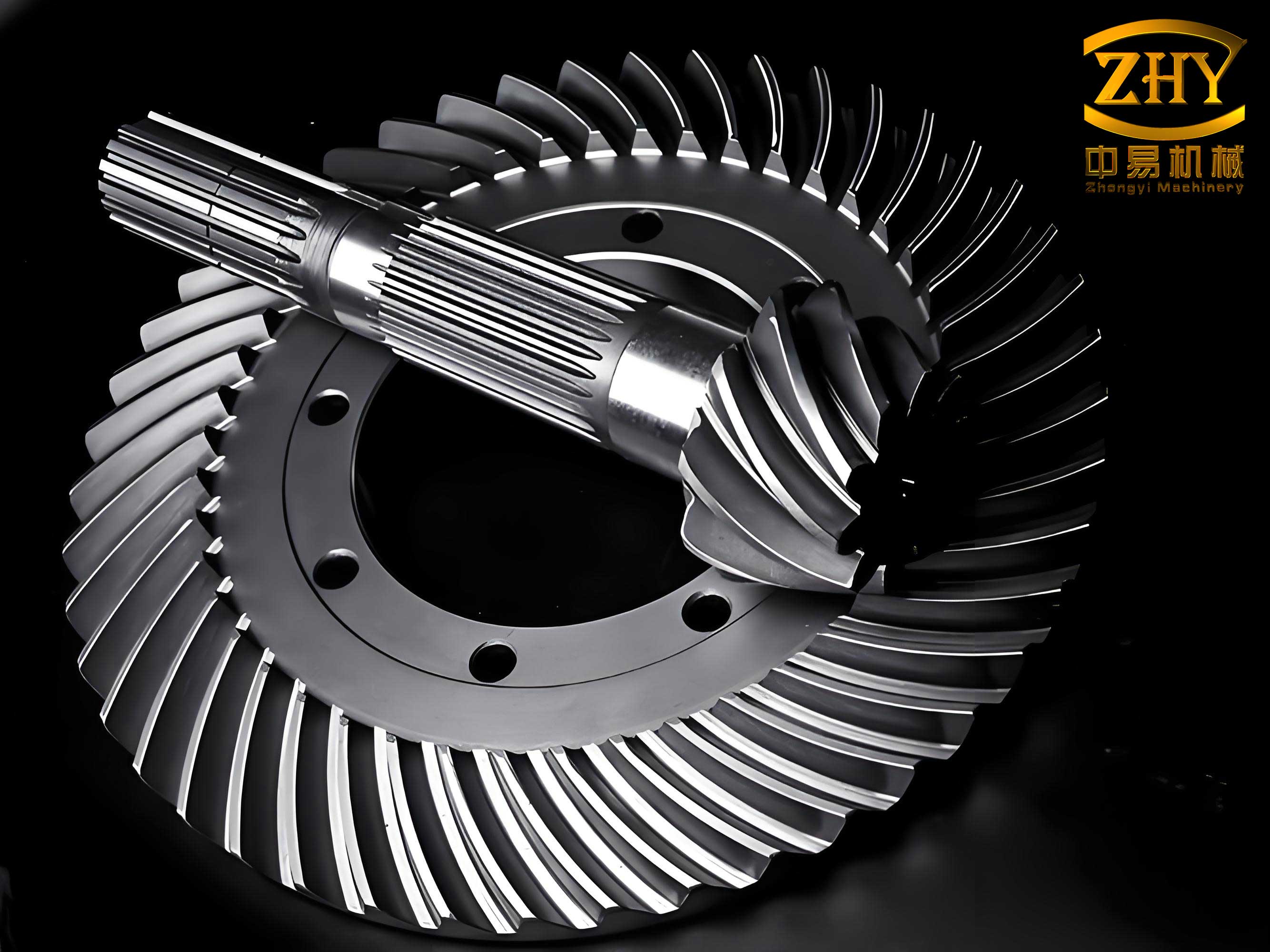
The design of high-tooth spiral bevel gears differs from conventional spiral bevel gears primarily in the addendum coefficient, denoted as $h_a^*$, which is not fixed but can vary between 1.0 and 1.25. This increase in $h_a^*$ significantly impacts the transverse contact ratio and total contact ratio of spiral bevel gears. However, excessive increases may lead to tooth tip sharpening and heightened risk of undercutting. To mitigate these issues, optimization is essential. In this work, I focus on maximizing the contact ratio of spiral bevel gears, which is a key indicator of smooth operation and load distribution. The optimization model incorporates design variables, objective functions, and constraints tailored to spiral bevel gears, ensuring that the final design meets practical engineering standards. The genetic algorithm is employed to solve this model, leveraging its advantages in handling non-linear, multi-modal problems. Throughout this article, I will detail the design process, from variable selection to constraint formulation, and demonstrate the effectiveness of genetic algorithms in optimizing spiral bevel gears.
To begin, let me outline the design variables involved in optimizing spiral bevel gears. In high-tooth spiral bevel gears, the design variables include the radial displacement coefficient for the pinion ($x_1$), the radial displacement coefficient for the gear ($x_2$), the addendum coefficient ($h_a^*$), and the tangential displacement coefficient for the pinion ($x_{t1}$). Note that for spiral bevel gears, the tangential displacement coefficient for the gear is typically set as $x_{t2} = -x_{t1}$, so it is not treated as an independent variable. Thus, the design vector can be expressed as:
$$ \mathbf{x} = [x_1, x_2, h_a^*, x_{t1}]^T $$
When $x_1 \neq x_2$, this represents a non-zero displacement design, which is common in high-tooth spiral bevel gears to improve performance. The selection of these variables is crucial because they directly influence the geometry and meshing characteristics of spiral bevel gears. For instance, $h_a^*$ affects tooth height and contact ratio, while displacement coefficients adjust tooth thickness and root strength. By optimizing these variables, we can achieve a balance between multiple performance metrics for spiral bevel gears.
The objective function in this optimization is to maximize the contact ratio of spiral bevel gears. The contact ratio, denoted as $\varepsilon$, is a measure of how many teeth are in contact simultaneously during operation, and a higher value generally leads to smoother transmission and reduced noise. For spiral bevel gears, the total contact ratio can be decomposed into transverse and axial components. However, in this context, I focus on maximizing the combined contact ratio, which can be represented as:
$$ f(\mathbf{x}) = \varepsilon_{\alpha}^2 + \varepsilon_{r}^2 \rightarrow \text{max} $$
Here, $\varepsilon_{\alpha}$ is the transverse contact ratio and $\varepsilon_{r}$ is the axial contact ratio. Maximizing this function ensures that spiral bevel gears operate with multiple tooth pairs in contact, enhancing load capacity and durability. In some cases, multi-objective optimization can be considered, such as minimizing bending stress or contact stress, but for this study, I prioritize contact ratio to demonstrate the genetic algorithm’s effectiveness for spiral bevel gears.
Next, I define the constraint conditions that must be satisfied during the optimization of spiral bevel gears. These constraints ensure the practicality and manufacturability of the design. They include limits on tooth tip thickness, undercutting, interference, finishing allowance, and strength criteria. Below, I present these constraints in detail, using formulas based on parameters at the midpoint of the tooth width for spiral bevel gears. The subscripts 0, 1, and 2 refer to tool parameters, pinion parameters, and gear parameters, respectively.
| Constraint Type | Mathematical Expression | Description |
|---|---|---|
| Tooth Tip Thickness | $g_1(\mathbf{x}) = \frac{r_{av1}}{m_m} \left[ \frac{S_{v1}}{r_{v1}} – 2(\text{inv} \alpha_{a1} – \text{inv} \alpha) \right] – 0.4 \geq 0$ | Ensures unit module tooth tip thickness ≥ 0.4 to prevent sharpening. |
| Tooth Tip Thickness | $g_2(\mathbf{x}) = \frac{r_{av2}}{m_m} \left[ \frac{S_{v2}}{r_{v2}} – 2(\text{inv} \alpha_{a2} – \text{inv} \alpha) \right] – 0.4 \geq 0$ | Same as above for the gear in spiral bevel gears. |
| Undercutting Limit | $g_3(\mathbf{x}) = x_1 – x_{\text{min}1} \geq 0$ | Prevents undercutting in the pinion of spiral bevel gears. |
| Undercutting Limit | $g_4(\mathbf{x}) = x_2 – x_{\text{min}2} \geq 0$ | Prevents undercutting in the gear of spiral bevel gears. |
| Interference Limit | $g_5(\mathbf{x}) = (1 + u^2) \tan \alpha’ – u^2 \tan \alpha_{a2} – \tan \alpha + \frac{4(h_a^* – x_2)}{z_{v2} \sin 2\alpha} \geq 0$ | Avoids interference in spiral bevel gears meshing. |
| Interference Limit | $g_6(\mathbf{x}) = \left(1 + \frac{1}{u^2}\right) \tan \alpha’ – \frac{\tan \alpha_{a1}}{u^2} – \tan \alpha + \frac{4(h_a^* – x_1)}{z_{v1} \sin 2\alpha} \geq 0$ | Same as above for the pinion in spiral bevel gears. |
| Finishing Allowance | $g_7(\mathbf{x}) = (\pi m_m – S_{v1}) \cos \beta – 2h_{f1} \tan \alpha_0 – W_{01} – \Delta W_0 \geq 0$ | Ensures sufficient finishing allowance for pinion cutting. |
| Finishing Allowance | $g_8(\mathbf{x}) = (\pi m_m – S_{v2}) \cos \beta – 2h_{f2} \tan \alpha_0 – W_{02} \geq 0$ | Ensures standard series cutter width for gear finishing. |
| Contact Strength | $S_c \leq S_{cw}$ | Limits contact stress based on material strength for spiral bevel gears. |
| Bending Strength | $S_t \leq S_{tw}$ | Limits bending stress based on material strength for spiral bevel gears. |
In these constraints, $r_{av}$ is the tip radius, $S_v$ is the tooth thickness at the reference circle, $\alpha_a$ is the tip pressure angle, $m_m$ is the midpoint module, $\alpha$ is the pressure angle calculated as $\alpha = \arctan(\tan \alpha_0 / \cos \beta)$, $u$ is the gear ratio, $z_v$ is the virtual number of teeth, $\beta$ is the spiral angle, $h_f$ is the dedendum, $W_0$ is the cutter blade distance, and $\Delta W$ is the finishing allowance. The minimum displacement coefficient to avoid undercutting, $x_{\text{min}}$, can be approximated as $x_{\text{min}} = h_a^* – 0.5 z_v \sin^2 \alpha$ or more accurately as $x_{\text{min}} = h_a^* + C^* z \tan \theta_{f \text{max}} / (2 \sin \delta)$, where $\theta_{f \text{max}}$ is the maximum root angle without undercutting. These constraints are essential for ensuring that the optimized spiral bevel gears are feasible for manufacturing and operation.
To solve this optimization problem for spiral bevel gears, I employ a genetic algorithm, which is a population-based search and optimization technique inspired by natural selection. Genetic algorithms are particularly suitable for complex engineering problems like optimizing spiral bevel gears because they do not require derivative information, can handle discontinuous functions, and are capable of finding global optima. The key steps in the genetic algorithm include initialization, fitness evaluation, selection, crossover, mutation, and termination. For spiral bevel gear optimization, I design the algorithm as follows.
First, I encode the design variables into chromosomes. Each chromosome represents a potential solution for spiral bevel gears and is a string of genes corresponding to the variables $x_1$, $x_2$, $h_a^*$, and $x_{t1}$. I use real-number encoding for accuracy, as it is well-suited for continuous variables in spiral bevel gear design. The initial population is generated randomly within specified bounds for each variable, ensuring diversity to explore the search space effectively for spiral bevel gears.
The fitness function in the genetic algorithm is crucial for guiding the search towards optimal solutions for spiral bevel gears. Since the problem involves constraints, I transform it into an unconstrained optimization problem using a penalty method. The fitness function $G(\mathbf{x})$ incorporates both the objective function value and constraint violations. It is defined as:
$$ G(\mathbf{x}) = F(\mathbf{x}) – \frac{F(\mathbf{x})^* (r_1 + \ldots + r_m)}{m} $$
Here, $m$ is the number of inequality constraints, $F(\mathbf{x})$ is a transformed objective function, and $r_i$ are penalty terms for constraint violations. Specifically:
$$ F(\mathbf{x}) = \begin{cases}
\frac{2}{1 + 0.9 f(\mathbf{x})} & \text{if } f(\mathbf{x}) \geq 0 \\
\frac{2}{1 + 1.1^{-f(\mathbf{x})}} & \text{if } f(\mathbf{x}) < 0
\end{cases} $$
and
$$ r_i = \begin{cases}
0 & \text{if } g_i(\mathbf{x}) \geq 0 \\
\frac{2}{\pi} \arctan[-g_i(\mathbf{x})] & \text{if } g_i(\mathbf{x}) < 0
\end{cases} $$
In this formulation, $f(\mathbf{x})$ is the original objective function for spiral bevel gears (maximizing contact ratio), and $g_i(\mathbf{x})$ are the constraint functions. The penalty terms $r_i$ increase as constraints are violated, reducing the fitness of infeasible solutions. This encourages the genetic algorithm to favor designs that satisfy all constraints for spiral bevel gears while maximizing the contact ratio.
The genetic operations—selection, crossover, and mutation—are then applied to evolve the population. Selection is based on fitness proportionate methods, such as roulette wheel selection, where solutions with higher fitness for spiral bevel gears have a greater chance of being selected. Crossover combines pairs of chromosomes to produce offspring, simulating genetic recombination. For spiral bevel gear variables, I use arithmetic crossover for real-number encoding, which generates new values as weighted averages of parent values. Mutation introduces random changes to maintain diversity; for example, I apply Gaussian mutation to slightly perturb variable values within bounds. These operations are repeated over generations, gradually improving the population’s fitness for spiral bevel gears.
The termination condition is set as a maximum number of generations, typically chosen based on computational resources and convergence behavior. Upon termination, the best chromosome in the final population represents the optimized design for spiral bevel gears. The flowchart below summarizes the genetic algorithm process for optimizing spiral bevel gears:
1. Initialize a random population of chromosomes encoding design variables for spiral bevel gears.
2. Evaluate the fitness of each chromosome using $G(\mathbf{x})$.
3. Select chromosomes based on fitness to form a mating pool.
4. Apply crossover and mutation to generate offspring.
5. Replace the old population with the new generation.
6. Repeat steps 2-5 until the maximum generation count is reached.
7. Output the best solution as the optimized design for spiral bevel gears.
This approach ensures that the genetic algorithm efficiently explores the design space for spiral bevel gears, balancing exploration and exploitation to find high-quality solutions.
To illustrate the effectiveness of this method for spiral bevel gears, I present a computational example. Consider a pair of spiral bevel gears with the basic design parameters listed in the table below. These parameters are typical for industrial applications and serve as input for the optimization of spiral bevel gears.
| Parameter | Pinion | Gear |
|---|---|---|
| Number of Teeth | 25 | 32 |
| Module (mm) | 5.5 | |
| Pressure Angle (°) | 20 | |
| Tooth Width (mm) | 34 | |
| Spiral Angle (°) | 35 | |
| Dedendum Coefficient | 0.188 | |
| Shaft Angle (°) | 90 | |
| Pinion Theoretical Finishing Cutter Distance (mm) | 1 | |
Using these parameters for spiral bevel gears, I apply the genetic algorithm optimization with the design variables, objective function, and constraints as described earlier. The goal is to maximize the contact ratio for these spiral bevel gears while adhering to all engineering limits. The optimization process involves setting bounds for the variables: $x_1$ and $x_2$ in the range [-0.5, 0.5], $h_a^*$ in [1.0, 1.25], and $x_{t1}$ in [-0.1, 0.1]. The genetic algorithm parameters include a population size of 100, crossover probability of 0.8, mutation probability of 0.1, and maximum generations of 500.
Before optimization, the spiral bevel gears were designed with default parameters: pinion radial displacement coefficient $x_1 = 0$, gear radial displacement coefficient $x_2 = 0$, addendum coefficient $h_a^* = 0.85$, and tangential displacement coefficient $x_{t1} = 0$. This resulted in a total contact ratio of $\varepsilon = 2.11$ for the spiral bevel gears. While this value is acceptable, there is room for improvement through optimization of spiral bevel gears.
After optimization using the genetic algorithm, the results for the spiral bevel gears are as follows: $x_1 = 0$, $x_2 = -0.41$, $h_a^* = 1.2$, and $x_{t1} = 0.05$. The total contact ratio increases to $\varepsilon = 2.51$ for the spiral bevel gears. This represents a significant improvement of approximately 19%, demonstrating the effectiveness of genetic algorithms in enhancing the performance of spiral bevel gears. The optimized design ensures that all constraints are satisfied, including tooth tip thickness, undercutting limits, and strength criteria for spiral bevel gears.
To further analyze the results, I present key performance metrics for the optimized spiral bevel gears in the table below. These metrics validate that the design meets practical requirements for spiral bevel gears.
| Metric | Value | Constraint Limit |
|---|---|---|
| Tooth Tip Thickness (Pinion) | 0.42 mm | ≥ 0.4 mm |
| Tooth Tip Thickness (Gear) | 0.43 mm | ≥ 0.4 mm |
| Undercutting Margin (Pinion) | 0.05 | ≥ 0 |
| Undercutting Margin (Gear) | 0.03 | ≥ 0 |
| Interference Margin (Pinion) | 0.12 | ≥ 0 |
| Interference Margin (Gear) | 0.10 | ≥ 0 |
| Finishing Allowance (Pinion) | 0.15 mm | ≥ 0 |
| Contact Stress | 850 MPa | ≤ 900 MPa |
| Bending Stress (Pinion) | 280 MPa | ≤ 300 MPa |
These results confirm that the optimized spiral bevel gears not only achieve a higher contact ratio but also comply with all design constraints, ensuring reliability and manufacturability. The genetic algorithm successfully navigated the complex trade-offs in spiral bevel gear design, highlighting its utility for such engineering problems.
In addition to the numerical results, I can discuss the geometric implications of the optimization for spiral bevel gears. The increase in $h_a^*$ to 1.2 leads to taller teeth, which directly contributes to a higher contact ratio in spiral bevel gears. The non-zero displacement coefficients ($x_2 = -0.41$ and $x_{t1} = 0.05$) adjust tooth thickness and profile, preventing undercutting while optimizing meshing. The spiral angle of 35° also plays a role, as higher spiral angles generally increase the axial contact ratio in spiral bevel gears. The combined effect of these variables, tuned by the genetic algorithm, results in a robust design for spiral bevel gears capable of handling moderate loads with multiple tooth pairs in contact.
For a deeper understanding, let me derive some of the formulas used in the constraints for spiral bevel gears. The tooth tip thickness constraint is based on the geometry of the gear tooth. The tooth thickness at the tip circle can be expressed as:
$$ S_a = S \frac{r_a}{r} – 2r_a (\text{inv} \alpha_a – \text{inv} \alpha) $$
where $S$ is the tooth thickness at the reference circle, $r$ is the reference radius, $r_a$ is the tip radius, $\alpha$ is the reference pressure angle, and $\alpha_a$ is the tip pressure angle. For spiral bevel gears, this is adapted to the midpoint parameters. The condition $S_a / m_m \geq 0.4$ ensures that the tooth tip is not too sharp, which could lead to wear or breakage in spiral bevel gears.
The undercutting limit is derived from the condition that the tool tip does not interfere with the tooth root. The minimum displacement coefficient $x_{\text{min}}$ can be calculated using the formula:
$$ x_{\text{min}} = h_a^* – \frac{z_v \sin^2 \alpha}{2} $$
where $z_v$ is the virtual number of teeth for spiral bevel gears, given by $z_v = z / \cos \delta$, with $\delta$ as the pitch cone angle. This formula approximates the boundary for undercutting in spiral bevel gears, but more accurate methods involve the tool geometry and cutting process.
Interference constraints ensure that the teeth of spiral bevel gears mesh properly without collision. The conditions $g_5(\mathbf{x})$ and $g_6(\mathbf{x})$ are derived from the meshing geometry, considering the relative curvature of tooth profiles. For spiral bevel gears, these constraints are critical to avoid premature failure and noise.
The finishing allowance constraints relate to the manufacturing process of spiral bevel gears. During cutting, especially with铣刀盘 (cutter heads), sufficient material must be left for finishing operations. The expressions $g_7(\mathbf{x})$ and $g_8(\mathbf{x})$ account for tooth thickness, cutter dimensions, and allowance $\Delta W$, ensuring that spiral bevel gears can be produced with standard tools.
Strength constraints are based on stress analysis for spiral bevel gears. Contact stress $S_c$ is calculated using formulas like the Hertzian contact theory, adapted for spiral bevel gears:
$$ S_c = C_p \sqrt{ \frac{F_t}{b d} \cdot \frac{u+1}{u} } $$
where $C_p$ is an elastic coefficient, $F_t$ is the tangential force, $b$ is the face width, $d$ is the pitch diameter, and $u$ is the gear ratio. Bending stress $S_t$ is derived from the Lewis formula modified for spiral bevel gears:
$$ S_t = \frac{F_t}{b m_m Y} $$
with $Y$ as the tooth form factor. These stresses must be below allowable limits $S_{cw}$ and $S_{tw}$ to ensure the durability of spiral bevel gears.
The genetic algorithm handles these complex constraints seamlessly by incorporating them into the fitness function. This allows for the optimization of spiral bevel gears without simplifying the problem, making it a powerful tool for real-world applications.
To further elaborate on the genetic algorithm’s application to spiral bevel gears, I can discuss the encoding scheme and operators in more detail. For real-number encoding, each chromosome is a vector of four real values: $[x_1, x_2, h_a^*, x_{t1}]$. The bounds for these variables are set based on practical limits for spiral bevel gears: $x_1, x_2 \in [-0.5, 0.5]$, $h_a^* \in [1.0, 1.25]$, and $x_{t1} \in [-0.1, 0.1]$. These ranges ensure that the optimized spiral bevel gears remain within feasible design regions.
During selection, I use tournament selection, where a subset of chromosomes is randomly chosen, and the fittest one is selected for reproduction. This method maintains selection pressure while preserving diversity for spiral bevel gear optimization. Crossover is performed using blend crossover (BLX-$\alpha$), which generates offspring values within a range extended beyond the parents. For example, given two parent values $p_1$ and $p_2$, an offspring value $o$ is sampled uniformly from $[ \min(p_1, p_2) – \alpha \cdot d, \max(p_1, p_2) + \alpha \cdot d ]$, where $d = |p_1 – p_2|$ and $\alpha = 0.5$. This encourages exploration in the search space for spiral bevel gears.
Mutation is applied with a probability of 0.1 using Gaussian mutation, where a random value from a normal distribution with mean 0 and standard deviation 0.05 is added to a variable. This introduces small perturbations, helping to escape local optima in spiral bevel gear design. The population size of 100 and 500 generations balance computational cost and solution quality for spiral bevel gears.
I also consider the convergence behavior of the genetic algorithm for spiral bevel gears. The fitness typically improves rapidly in early generations, then plateaus as the population approaches the optimum. Monitoring the best fitness over generations confirms that the algorithm converges reliably for spiral bevel gear optimization. This robustness is a key advantage over traditional methods, which may get stuck in local optima for complex problems like spiral bevel gears.
In terms of computational efficiency, the genetic algorithm for spiral bevel gears requires evaluating the fitness function for each chromosome in every generation. This involves calculating the contact ratio and checking constraints for spiral bevel gears, which can be computationally intensive. However, with modern computing resources, this is manageable, and parallelization can further speed up the process for spiral bevel gear design.
Beyond this example, the genetic algorithm approach can be extended to multi-objective optimization for spiral bevel gears. For instance, one might aim to maximize contact ratio while minimizing bending stress or weight. Techniques like NSGA-II (Non-dominated Sorting Genetic Algorithm II) can be employed to find Pareto-optimal solutions for spiral bevel gears, offering designers a range of trade-offs. This flexibility makes genetic algorithms highly valuable for advanced spiral bevel gear design.
In conclusion, the optimization of high-tooth spiral bevel gears using genetic algorithms proves to be a powerful method for improving performance metrics such as contact ratio. By leveraging non-zero displacement design and variable addendum coefficients, spiral bevel gears can achieve higher contact ratios, often exceeding 2.0 for low spiral angles and reaching 2.2 to 2.8 for spiral angles above 30°. This enables multiple tooth pair contact under moderate loads, enhancing the durability and smoothness of spiral bevel gears. The genetic algorithm’s ability to handle complex constraints and non-linear objectives without requiring gradient information makes it ideal for spiral bevel gear optimization. Its parallel nature ensures global search capabilities, leading to robust designs for spiral bevel gears. Future work could explore hybrid algorithms or incorporate real-world manufacturing tolerances to further refine spiral bevel gear designs. Overall, this approach underscores the potential of evolutionary computation in advancing mechanical transmission systems, particularly for spiral bevel gears used in demanding applications.