Let the mass of non-circular gear be m and the speed be m ω, The angular acceleration is ε, If the distance between the center of mass and the center of rotation is R and the moment of inertia is j, then the inertia force F and the moment of inertia m of the non-circular gear are respectively:
According to the transmission design requirements, the maximum speed of non-circular driving gear ω Z is 2 500 R / min, corresponding to the maximum speed of non-circular driven gear ω C is 3 350 R / min, it can be seen that the huge inertia load of non-circular gear at the highest speed has a self-evident impact on the transmission performance and efficiency of the transmission. Therefore, it is necessary to eliminate the inertia load as much as possible by removing the eccentric load mass and thinning the tooth thickness at individual positions to ensure the transmission stability.
1. Optimization design method based on SolidWorks

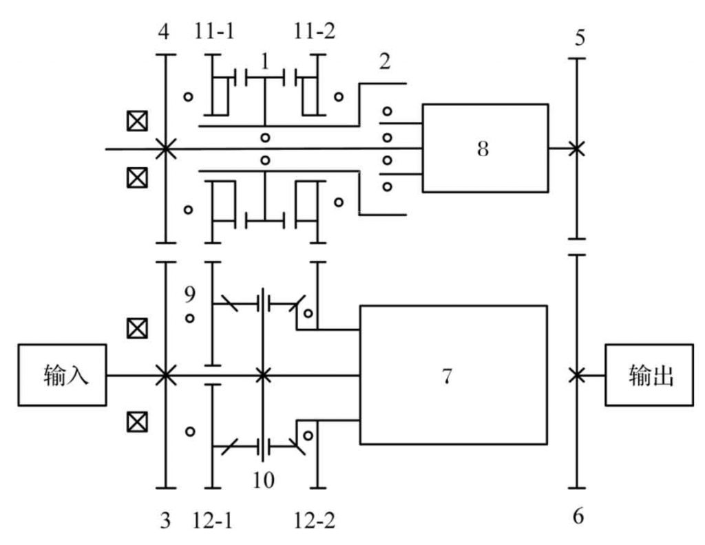
It can be seen from Figure 1 that a certain surface of each non-circular gear needs to fit with the corresponding AXK series thrust bearing washer during assembly, so the groove opened for static balance cannot extend to this surface, that is, the groove is non-pass groove. In addition, the transmission structure makes the spline parameters of each non-circular gear slightly different, and the gear model is more complex
Programming calculation does not necessarily improve the design efficiency, while solid Works software is easier to get the centroid position of the parts, and its design example function can quickly realize the structural optimization of the mathematical model by using the iterative method, which is suitable for the static balance design of non-circular gears.
1) Add sensors. Set the rotation center of the non-circular gear 3D model as the origin, add sensors, set the type as the quality attribute, and set the attribute as the mass center x, that is, the abscissa of the centroid plane is monitored. Repeat this step to set the attribute to the center of mass y, that is, the ordinate of the centroid plane is monitored. For non-circular gears, the center distance a is much larger than the gear thickness D, so there is no need to monitor the spatial coordinate Z.
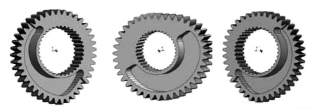
2) Determine the slotting parameters. In order to ensure that the optimized design of non-circular gear can still meet the requirements of various working conditions, a groove is cut on the offset side of the center of mass. The groove is surrounded by two straight sides and two curved sides, and the included angles of the two straight sides and the vertical line are 0 α、β, The two curved edges are equidistant lines of spline indexing circle and tooth profile pitch curve. In order to ensure the processability, the sharp edge of groove needs to be chamfered with radius R and groove depth h (as shown in Figure 2).
3) The parameters of thinning tooth thickness are determined. For the gear with larger spline, the non-pass groove can not effectively improve the position of the center of mass, and the tooth thickness on the offset side of the center of mass needs to be reduced. The profile of the reduced tooth thickness is composed of the curved edge of the groove, the tooth profile of the non-circular gear and two straight edges, and the included angles of the two straight edges and the vertical line are respectively 0 γ、φ, The thinning depth is l (as shown in Figure 3).
4) Optimization calculation. When optimizing, select α、β、 h、 γ、φ、 l. R is a variable; Considering that the radius of milling cutter used for chamfering should be greater than a certain value, R can be limited in a certain range as a constraint condition; Taking the centroid coordinate exactly equal to (0,0) as the objective function, the optimization ratio of abscissa and ordinate is 5 ∶ 5.
2. Selection of gear variables and optimization results
According to the structural arrangement of the transmission and the dimension parameters of shaft parts shown in Figure 1, when a = 160 mm and d = 40 mm, the slotted surface of the third non-circular driving gear is inconsistent with that of the third non-circular driven gear. In order to ensure that the meshing line length of the gear is not too small, only the tooth thickness of the latter is thinned.
3. Comparative analysis before and after optimization
Through the optimization design, the mass of each non-circular gear is reduced by more than 33.2%, the moment of inertia is reduced by more than 33.3%, and the maximum moment of inertia is reduced by more than 33.3%, especially in the optimization of inertial force, which is only 0.183% ~ 0.828% before optimization. Considering the machining error, it can be considered that the influence of inertial force on transmission is eliminated, The optimized three-dimensional model of each gear is shown in Figure 4


