
Abstract
The churning resistance of hypoid gear in automotive rear axles to improve mechanical transmission efficiency. A three-dimensional computational fluid dynamics (CFD) model was developed using the Volume of Fluid (VOF) multiphase model and the standard k−εk−ε turbulence model. The churning power loss mechanism of hypoid gear was analyzed, leading to structural improvements such as replacing bolt connections with laser-welded joints and adding baffle plates. Fluent simulations and experimental validations confirmed that these modifications significantly reduce churning resistance, with a maximum drag reduction of 35.9% at higher rotational speeds. Comparative analysis with empirical formulas highlighted their limitations in predicting optimized hypoid gear performance.
Keywords: Hypoid gear, Churning resistance, CFD, VOF, Drag reduction
1. Introduction
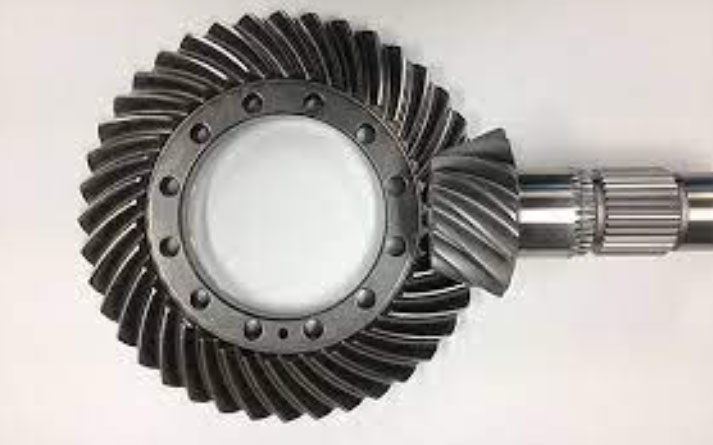
The rapid growth of the automotive industry has intensified demands for energy-efficient and environmentally friendly drivetrains. Hypoid gear, widely used in rear axles due to their high torque capacity and smooth operation, contribute significantly to power losses through churning resistance. Studies indicate that churning losses can exceed 50% of total gear system losses at high speeds, underscoring the need for optimization.
Previous research on gear churning has primarily focused on spur and helical gears, leaving hypoid gear—with their complex geometry and skewed tooth contact—understudied. This work bridges this gap by combining CFD simulations, empirical validations, and structural innovations to address churning resistance in hypoid gear.
2. CFD Model Development
2.1 Geometry Simplification and Mesh Generation
The rear axle assembly was simplified by removing non-essential components (e.g., bearings, shafts) and retaining critical parts: hypoid gear, differential housing, and bolts. The fluid domain was extracted using Boolean operations.
| Component | Treatment |
|---|---|
| Hypoid gear | Retained with 50 mm oil immersion depth |
| Bolts | Initially included, later removed |
| Baffle plates | Added post-optimization |
| Differential housing | Simplified surfaces |
HyperMesh generated an unstructured tetrahedral mesh with 1,092,289 elements and 196,092 nodes. Mesh independence was verified to ensure accuracy.
2.2 Fluid Parameters and Boundary Conditions
The VOF model tracked the air-oil interface, while the k−εk−ε turbulence model resolved turbulent flows. Key parameters include:
| Fluid | Density (kg/m³) | Dynamic Viscosity (kg/m·s) | Temperature (°C) |
|---|---|---|---|
| Lubricant oil | 839.8 | 0.48 | 50 |
| Air | 1.225 | 1.7894×10−51.7894×10−5 | 50 |
Boundary conditions were defined as:
- Stationary walls: Rear axle housing, differential housing.
- Rotating walls: Hypoid gear, bolts (pre-optimization).
- Pressure outlets: Atmospheric pressure at axle ends.
The initial oil distribution and rotational motion were controlled via user-defined functions (UDFs).
3. Churning Resistance Mechanism
3.1 Pressure and Velocity Fields
At 887 rpm, the hypoid gear teeth generated high dynamic pressure (PmaxPmax) on their leading faces and low pressure on trailing faces. The pressure differential (ΔPΔP) created fluid resistance, while high velocities (VmaxVmax) at gear tips increased kinetic energy dissipation.ΔP=Pleading−PtrailingΔP=Pleading−Ptrailing
Bolt-induced vortices further amplified turbulence, contributing to additional power loss.
3.2 Structural Optimization
Two modifications were implemented:
- Bolt removal: Replaced bolt connections with laser-welded joints.
- Baffle plates: Added 18 mm gap plates to suppress oil splashing.
4. Results and Validation
4.1 Simulation vs. Experiment
Churning torque (TT) was measured across speeds (133–1,065 rpm). Results showed strong agreement between CFD and experiments (Table 1).
| Speed (rpm) | Pre-Optimization | Post-Optimization | Drag Reduction (%) |
|---|---|---|---|
| 133 | 0.23 N·m | 0.16 N·m | 30.4 |
| 887 | 1.03 N·m | 0.66 N·m | 35.9 |
| 1065 | 1.18 N·m | 0.78 N·m | 33.9 |
4.2 Key Performance Metrics
- Dynamic pressure: Reduced by up to 54% (Table 2).
- Fluid velocity: Decreased by 6% (Table 2).
| Speed (rpm) | PmaxPmax (Pa) | VmaxVmax (m/s) |
|---|---|---|
| Pre-887 | 14,805 | 9.67 |
| Post-887 | 6,832 | 9.38 |
4.3 Empirical Formula Limitations
Existing formulas (e.g., Kahraman et al. [9]) correlated well with pre-optimization data but underestimated post-optimization churning torque due to unaccounted flow suppression from baffles.
5. Discussion
- Hypoid Gear Geometry: Skewed teeth inherently increase churning resistance compared to spur gears.
- Speed Dependency: Drag reduction efficacy improves with speed due to enhanced flow control.
- Baffle Design: Optimal gap (0.2× gear radius) balances drag reduction and lubrication.
6. Conclusion
- Bolt removal and baffle integration reduce hypoid gear churning resistance by up to 35.9%.
- CFD simulations align with experiments but require recalibration for non-bolted configurations.
- Future work should explore hybrid baffle designs and multi-phase thermal effects.