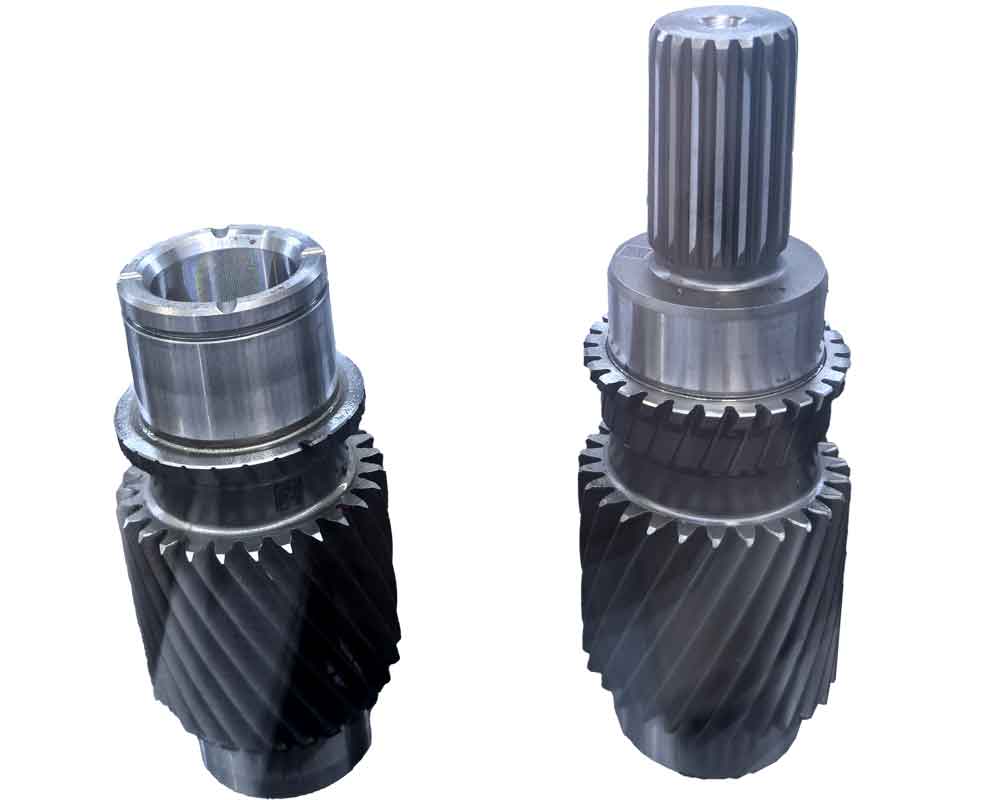
In contemporary gear manufacturing, workpiece blanks undergo multiple cutting passes during tooth profile generation, with cutting depths typically determined by empirical methods. This approach lacks theoretical foundation, often resulting in uneven force distribution across cutting cycles that accelerates tool wear, causes machine tool damage, increases noise/vibration, and reduces operational efficiency. Through systematic analysis of gear shaping processes, we establish a mathematical model for cutting force optimization that resolves these challenges while providing a reference framework for further research.
Standard Parameter Configuration in Gear Shaping Operations
Modern shaping machine interfaces incorporate fundamental parameters including tooth count, module, and internal/external gear designation. The total cutting cycle count (tool jump frequency) is determined by full tooth depth (H): typically 1-2 cycles for H ≤ 5mm, and 3-5 cycles for 5mm < H ≤ 10mm. The maximum cutting area per cycle is constrained by the machine’s designed power capacity as specified in technical documentation. Unoptimized depth settings cause significant force fluctuations during intermittent cutting operations, accelerating tool degradation and potentially causing catastrophic failure. Suboptimal parameters also manifest as excessive noise and vibration, compromising machining accuracy and machine longevity. Traditionally, operators perform time-consuming empirical adjustments considering tool durability, precision requirements, and dynamic response characteristics.

Fundamental Calculations for Involute Gear Geometry
Critical geometric relationships govern gear cutting processes, where \( r \) denotes pitch circle radius, \( r_b \) base circle radius, \( r_y \) arbitrary circle radius, \( r_a \) addendum radius, and \( r_f \) dedendum radius. The arc tooth thickness at any circle is expressed as:
$$ L_y = L \frac{r_y}{r} – 2r_y [\text{inv}(\alpha_y) – \text{inv}(\alpha)] $$
where \( \alpha \) represents standard pressure angle, \( \alpha_y \) pressure angle at \( r_y \), and involute function \( \text{inv}(\alpha) = \tan\alpha – \alpha \frac{\pi}{180} \). Fundamental parameters are derived as:
| Parameter | Expression |
|---|---|
| Base radius | \( r_b = m z \cos\alpha \) |
| Pitch radius | \( r = \frac{m z}{2} \) |
| Addendum radius | \( r_a = r + m h_a \) |
| Dedendum radius | \( r_f = r – m (h_a + h_f) \) |
where \( m \) = module, \( z \) = tooth count, \( h_a \) = addendum coefficient, \( h_f \) = dedendum coefficient. The cross-sectional area per tooth is:
$$ S_{\text{tooth}} = \int_{r_f}^{r_a} \left[ L \frac{r_y}{r} – 2r_y (\text{inv}(\alpha_y) – \text{inv}(\alpha)) \right] dr_y $$
Total material removal area for complete gear generation becomes:
$$ S = \pi (r_a^2 – r_f^2) – z S_{\text{tooth}} $$
Cutting Process Simulation and Analysis
Shaping utilizes generation motion where cutter and blank synchronize to envelope the tooth profile. Cutting area variation at different depths significantly impacts force dynamics. As illustrated in the tool envelope diagram, progressive depth increments yield non-uniform material removal rates. For two-pass gear cutting, unequal area distribution between passes creates substantial force differentials that detrimentally affect system stability. Optimized depth allocation is therefore critical for consistent machining performance.
Cutting Area Calculation Methodology
Gear cutting fundamentally involves radial feed motion followed by generating movement. When cutting at offset \( h \) from theoretical position, the arc tooth thickness at cutting depth follows:
$$ L_h = \frac{\pi m}{2} $$
Deviation from standard tooth thickness is approximated as:
$$ \Delta L \approx h \tan\alpha $$
The material removal area at depth \( h \) is derived as:
$$ S_h = \pi [r_a^2 – (r_f + h)^2] – 2z (r_a – r_f – h)h \tan\alpha – z \int_{r_f + h}^{r_a} \left[ L \frac{r_y}{r} – 2r_y (\text{inv}(\alpha_y) – \text{inv}(\alpha)) \right] dr_y $$
Determination of Optimal Feed Depth Sequence
For multi-pass gear cutting with total depth \( H \) distributed over \( n \) cycles, depth relationships are:
$$ t_1 + t_2 + \cdots + t_n = H $$
$$ h_k = H – \sum_{i=1}^{k} t_i \quad (k=1,2,\ldots,n) $$
Material removal per pass is calculated sequentially:
$$ S_1 = S_{h_1} $$
$$ S_k = S_{h_k} – S_{h_{k-1}} \quad (k=2,3,\ldots,n) $$
To maintain constant cutting force, equal area removal per pass is essential:
$$ S_1 = S_2 = \cdots = S_n = \frac{S}{n} $$
This yields the cumulative area constraint:
$$ S_{h_k} = \frac{k}{n} S \quad (k=1,2,\ldots,n) $$
Computational Case Study
Implementation for gear parameters: \( m = 4 \), \( z = 45 \), \( \alpha = 20^\circ \), \( h_a = 1 \), \( h_f = 0.25 \):
| Cutting Passes | Depth Allocation (mm) | Area per Pass (mm²) |
|---|---|---|
| Single-pass | \( t_1 = 9.00 \) | 2530.5 |
| Two-pass | \( t_1 = 6.37 \), \( t_2 = 2.63 \) | 1265.25 |
| Three-pass | \( t_1 = 5.20 \), \( t_2 = 2.15 \), \( t_3 = 1.65 \) | 843.5 |
Industrial Implementation and Conclusions
As automation and intelligence transform industrial manufacturing, scientific parameter selection becomes crucial for quality, efficiency, and cost control. Our gear cutting optimization model establishes a theoretical foundation for depth distribution by:
- Deriving cutting area equations for arbitrary depths
- Enforcing equal material removal per pass
- Maintaining consistent cutting forces
This methodology enables direct integration into CNC systems, providing intelligent parameter selection for gear cutting processes. The approach significantly enhances tool life, improves surface quality, reduces machine vibration, and increases production efficiency. Future research will extend this framework to helical and bevel gear cutting applications while incorporating real-time adaptive control.
