
In the process of forming helical gear by precision forging, friction will inevitably occur between the blank and the die and inside the blank in the process of plastic deformation. The friction in plastic forming is mainly caused by metal flow. Because the metal flow is irregular, the friction at each point in the forming process is often different. Taking the forming process of the driven helical gear of the automobile rear axle as an example, in the forming process, the forming process of the helical gear part depends on the transverse flow of the helical gear blank metal of the helical gear part along the tooth cavity of the upper die. In this process, the huge load generated by the downward movement of the upper die acts on the upper surface of the blank, so the friction factor becomes an important factor affecting the friction between the helical gear blank and the die. If the friction factor is too large, the friction between the helical gear blank and the die will be greater than the internal friction of the blank, and the helical gear blank will adhere to the die surface, resulting in defects in the forging and even wear on the die surface. Metal plastic processing is generally carried out at a higher temperature, which is more common, Therefore, the use of lubricant in the machining process has a particularly important impact on the quality of forgings.
1. Optimal simulation experiment scheme of friction factor
The research object of this group of experiments is the friction factor. The forging temperature is 800 ℃, the blank size is the helical gear blank with inner diameter of 125 mm, outer diameter of 175 mm, height of 33.5 mm and upper surface cone angle of 18 °, the movement speed of the upper die is set to 12.5 mm / s, and the friction factors are set to 0.1, 0.25, 0.4, 0.55 and 0.7 respectively.
2. Analysis of travel load curve
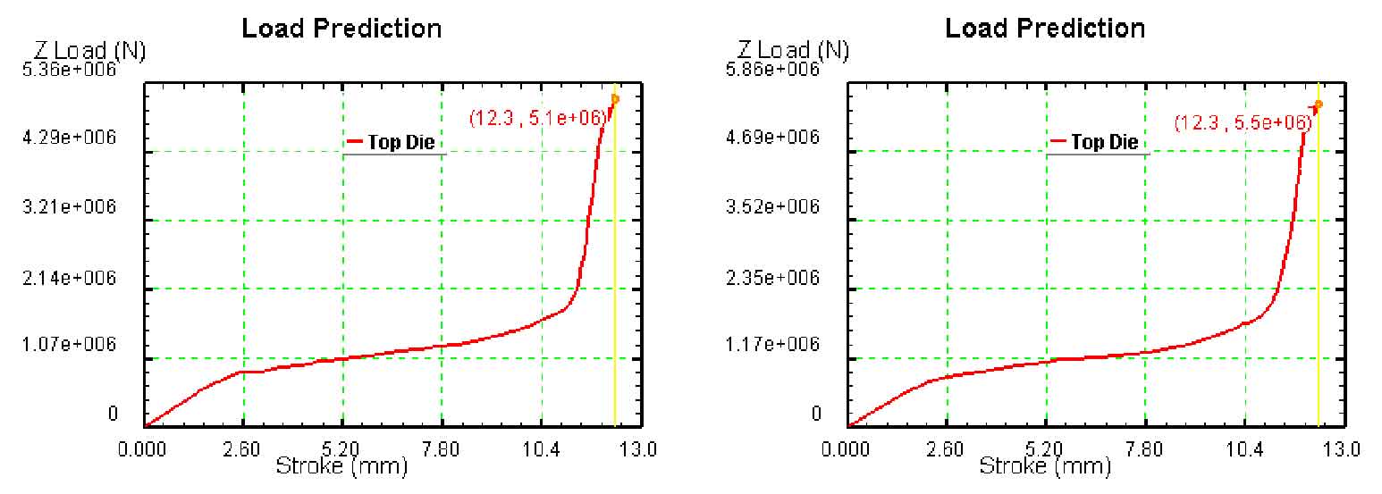
(b) Stroke load curve with friction factor of 0.25
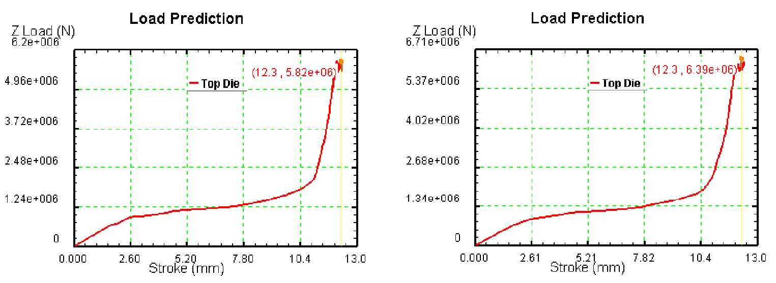
(d) Stroke load curve with friction factor of 0.55
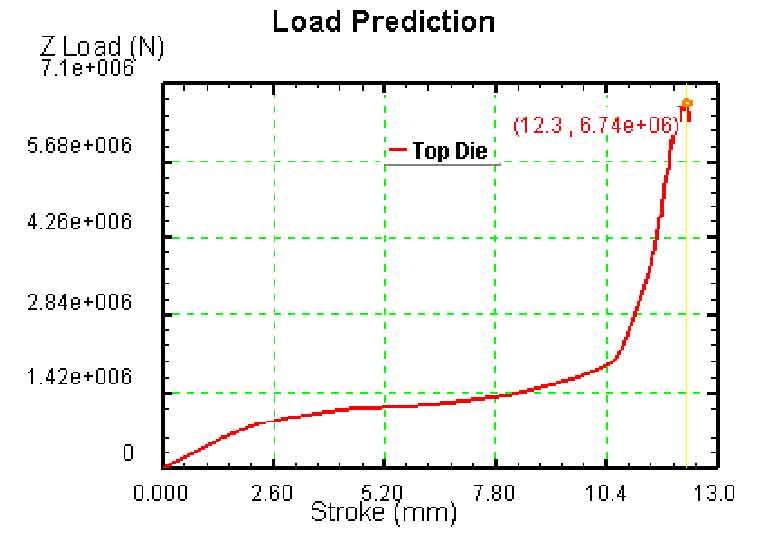
Figure (a) shows the travel load curve with friction factor of 0.1, figure (b) shows the travel load curve with friction factor of 0.25, figure (c) shows the travel load curve with friction factor of 0.4, figure (d) shows the travel load curve with friction factor of 0.55, and figure (e) shows the travel load curve with friction factor of 0.7. It can be seen from figure 3.13 that the law of stroke load curve under different friction factors is basically the same. After the upper die starts to move down, the load increases with the increase of stroke, and the relationship between load and stroke is basically linear. When the stroke reaches 11 mm, the load increases rapidly until the load reaches the maximum when closing the die. The maximum load under different friction factors is different. Table 3.5 shows the maximum load under different friction factors. It can be seen from the table that the maximum load increases with the increase of friction factor. Good lubrication conditions can reduce the friction factor in the machining process and reduce the load in the machining process, so as to avoid defects in the machining process, improve the quality of helical gear forgings and improve the service life of dies. Therefore, in the precision forging process of the driven helical gear of the automobile rear axle, the use of water graphite to lubricate the die can improve the surface quality of the helical gear forging and prolong the service life of the die.
| Friction factor | 0.1 | 0.25 | 0.4 | 0.55 | 0.7 |
| Maximum load (KN) | 5100 | 5500 | 5820 | 6390 | 6740 |