
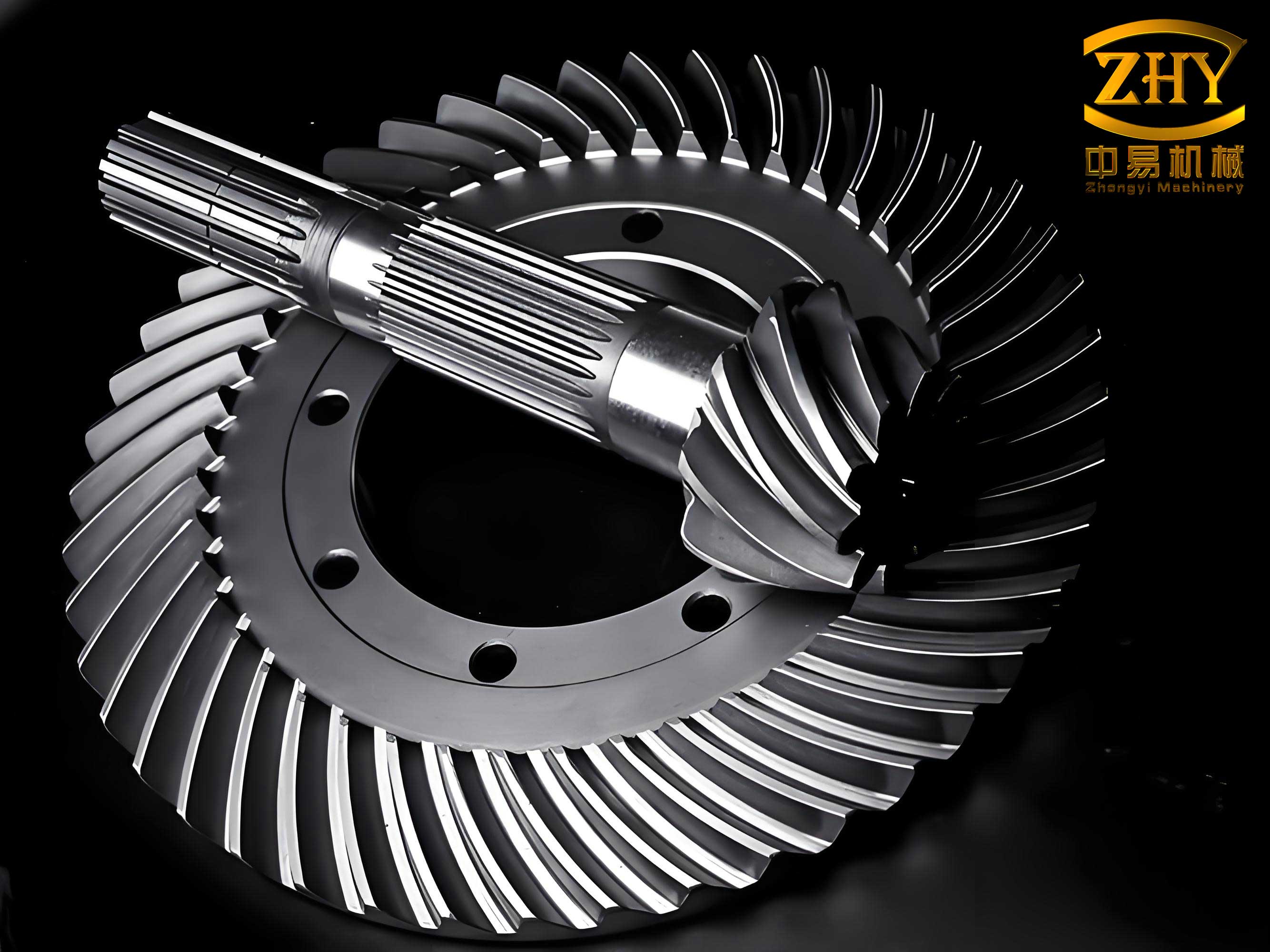
In the field of power transmission, the performance of spiral bevel gears is paramount. As an engineer deeply involved in gear manufacturing, I have consistently focused on the critical interplay between design, metallurgy, and thermal processing. The contact pattern—its location, size, and shape on the tooth flank—is the ultimate arbiter of a gear pair’s performance, governing noise, load capacity, and service life. Achieving a specified pattern post-machining is challenging enough; preserving its stability through the transformative and often distortive process of case hardening is a significant engineering hurdle. This discussion delves into the heart of this challenge, exploring the nuances of carburizing and quenching processes and their profound impact on the contact pattern stability of spiral bevel gears.
The Critical Importance of the Contact Pattern
The contact pattern is not merely a visual indicator; it is a functional signature. For spiral bevel gears transmitting motion between perpendicular axes, a correctly positioned and sized contact area ensures smooth load transfer, minimizes stress concentrations, and reduces vibration and noise generation. Typical specifications for a nominal contact pattern are stringent, often defined as follows:
| Parameter | Specification |
|---|---|
| Location (Face Width) | Centered, with slight bias towards the toe permissible. |
| Location (Tooth Height) | Centered on the active profile. |
| Shape | Elliptical or oval, with smooth boundaries. |
| Size (Length) | Typically 50-70% of the face width. |
| Size (Height) | Typically 50-70% of the tooth working depth. |
Deviations from this ideal—such as edge contact, pattern run-off to the heel or toe, or a “biased” pattern—lead to premature failure, elevated noise, and unacceptable performance. The complexity of the spiral bevel gear’s geometry, with its curved teeth and varying pressure angles, makes its response to thermal stress during heat treatment particularly sensitive and difficult to predict.
The Heat Treatment Challenge: Distortion vs. Pattern Stability
Carburizing and quenching are essential for imparting high surface hardness and a tough core to spiral bevel gears. However, the non-uniform thermal gradients and phase transformations (austenite to martensite) introduce internal stresses that manifest as geometric distortion. This distortion alters the tooth geometry, thereby shifting the contact pattern. The primary goal of heat treatment process design is not to eliminate distortion entirely—an often impossible task—but to control it predictably and minimize its detrimental effect on the contact pattern. The two primary quenching methods, free quenching (oil quenching) and press quenching (die quenching), present a fundamental trade-off.
Direct Quenching vs. Press Quenching: A Comparative Analysis
Our investigations began with a specific case: a spiral bevel gear with a 300mm diameter and 38mm thickness. We subjected identical lots of gears to both quenching methodologies and meticulously measured the outcomes.
1. Direct (Free) Quenching Process:
In this method, gears are cooled directly in oil without mechanical constraint. The results were characterized by significant geometric variation but relatively consistent contact patterns.
| Metric | Range | Population % | Contact Pattern Observation |
|---|---|---|---|
| Flatness | > 0.20 mm | 5% | Pattern location and shape were relatively stable and acceptable across the batch. The primary issue was not pattern shift, but overall geometric distortion (flatness & runout). |
| 0.15 – 0.20 mm | 15% | ||
| < 0.15 mm | 80% | ||
| Pitch Runout | > 0.15 mm | 1% | |
| 0.10 – 0.15 mm | 17% | ||
| < 0.10 mm | 82% |
2. Press (Die) Quenching Process:
This method uses a multi-actuator die (typically with an expanding mandrel, an upper inner ring, and an upper outer ring) to physically constrain the gear during cooling. The initial results showed excellent control over macro-geometry but disastrous instability in the contact pattern.
| Metric | Range | Population % | Contact Pattern Observation |
|---|---|---|---|
| Flatness | > 0.20 mm | 0% | Pattern stability was very poor. Both concave and convex flanks exhibited “long-and-short tooth” phenomena (uneven contact across the face width). Pattern location varied randomly in both lengthwise and profile directions. |
| 0.15 – 0.20 mm | 5% | ||
| < 0.15 mm | 95% | ||
| Pitch Runout | > 0.15 mm | 0% | |
| 0.10 – 0.15 mm | 3% | ||
| < 0.10 mm | 97% |
This stark contrast highlighted a critical insight: Press quenching effectively controls overall distortion metrics (flatness, runout), but the very act of mechanical constraint can introduce asymmetric, unpredictable stresses that catastrophically destabilize the contact pattern in spiral bevel gears. The pattern instability was the direct and primary consequence of distortion induced by the press quenching process itself.
Deconstructing Press Quenching Distortion: Mechanisms and Variables
To solve this, we had to understand the mechanics. During press quenching, the gear contracts thermally and undergoes phase transformation. The die applies counterforces. If these forces are not perfectly balanced with the gear’s internal stress state, they cause non-uniform plastic deformation. The final tooth form is a superposition of the machined form, thermal shrinkage distortion, phase transformation expansion, and die-induced deformation. The governing relationship can be conceptually simplified as:
$$ \Delta G_{final} = \Delta G_{thermal} + \Delta G_{phase} + \Delta G_{die} $$
Where:
$\Delta G_{final}$ = Final geometric deviation from nominal.
$\Delta G_{thermal}$ = Distortion due to non-uniform cooling and thermal stress.
$\Delta G_{phase}$ = Volumetric change due to austenite-to-martensite transformation ($\approx$ 1-4% volume increase).
$\Delta G_{die}$ = Plastic deformation imposed by the die contact forces.
For spiral bevel gears, the variable wall thickness (thin at the toe, thicker at the heel) and complex curvature mean $\Delta G_{thermal}$ and $\Delta G_{phase}$ are inherently non-uniform. The challenge is to configure the die and process so that $\Delta G_{die}$ compensates for the other terms in a predictable, repeatable manner, rather than adding another layer of random variation.
Systematic Optimization of Press Quenching for Spiral Bevel Gears
We embarked on a comprehensive series of designed experiments, varying key parameters to isolate their effects on contact pattern stability for our specific 300mm gear.
1. Carburizing Temperature (Tcarb):
We tested a range from 890°C to 930°C. Temperature directly influences austenite grain size, case depth kinetics, and the thermal gradient at the start of quenching. The relationship for case depth (d) is often approximated by:
$$ d \propto \sqrt{t} \cdot \exp\left(-\frac{Q}{RT_{carb}}\right) $$
where $t$ is time, $Q$ is activation energy, and $R$ is the gas constant. Higher temperatures increase diffusivity but also increase thermal stress and grain growth potential. We found 910°C provided the optimal balance: sufficient carburizing activity without excessive thermal shock or grain coarseness that could amplify distortion.
2. Quenching Pressures and Force Balance:
This was the most critical factor. We tested pressures from 0 to 35 N on each actuator (Expander, Upper Inner, Upper Outer). The force balance defines the stress state within the gear during plastic deformation. An incorrect balance, such as excessive inner pressure, could artificially “dome” the gear, drastically altering tooth lead. The optimal configuration was:
| Actuator | Optimal Pressure (N) | Primary Function |
|---|---|---|
| Expanding Mandrel | 35 | Controls bore size and concentricity. |
| Upper Inner Ring | 15 | Controls flatness of the inner land area. |
| Upper Outer Ring | 20 | Controls flatness of the outer rim and tooth root alignment. |
This specific ratio (35:15:20) was crucial for our gear geometry.
3. Pressure Application Points (Die Contact Geometry):
The location where the die contacts the gear is as important as the force. We designed and tested multiple die shoe geometries. The optimal configuration applied pressure strategically to the back face of the gear, avoiding direct contact with the fragile tooth tips and focusing on the rigid web and rim structures to guide distortion controllably. The principle is to minimize bending moments on the tooth-bearing section.
4. Gear Orientation in the Fixture:
We tested both “tooth-up” and “tooth-down” orientations. The orientation affects gravity-induced sag during transfer and the uniformity of oil flow during quenching. The “tooth-up” (concave side facing upward) orientation yielded significantly more repeatable results, likely due to more consistent, symmetrical cooling of the critical tooth profiles.
5. Press Quenching Time (thold):
This is the duration the gear is held under pressure in the die during cooling. We tested times from 2 to 5 minutes. Insufficient time allows the gear to distort after pressure release while it is still at a temperature where it is mechanically weak. Excessive time is inefficient. The cooling curve can be modeled, and the “hold” time must extend past the Martensite Finish (Mf) temperature for the core material. We found 5 minutes ensured the gear was cooled below 150°C before pressure release, locking in the desired geometry. The required time can be estimated from the part’s Biot number and the heat transfer coefficient (h) of the quenching medium:
$$ t_{hold} \approx f\left( \frac{V}{A}, \frac{h}{k}, \Delta T \right) $$
where $V/A$ is the volume-to-surface-area ratio, $k$ is thermal conductivity, and $\Delta T$ is the temperature difference.
The Optimized Process and Validated Results
Synthesizing the findings from these multivariable experiments, we established the following optimized press quenching protocol for this family of spiral bevel gears:
| Process Parameter | Optimal Setting |
|---|---|
| Carburizing Temperature | 910 °C |
| Expander Pressure | 35 N |
| Upper Inner Ring Pressure | 15 N |
| Upper Outer Ring Pressure | 20 N |
| Press Quenching Hold Time | 5 minutes |
| Gear Orientation in Fixture | Tooth-Up (Concave side up) |
| Die Contact Geometry | Optimized shoe design for web/rim contact |
Implementation of this optimized process yielded a dramatic improvement. Batch production data confirmed that we successfully resolved the trade-off, achieving both excellent geometric control and outstanding contact pattern stability.
| Metric | Range | Population % | Contact Pattern Observation |
|---|---|---|---|
| Flatness | > 0.20 mm | 0% | Contact pattern stability was excellent and highly repeatable. Patterns were consistently located in the nominal zone with the correct shape and size, meeting all specification requirements. |
| 0.15 – 0.20 mm | 3% | ||
| < 0.15 mm | 97% | ||
| Pitch Runout | > 0.15 mm | 0% | |
| 0.10 – 0.15 mm | 2% | ||
| < 0.10 mm | 98% |
Conclusion: A Holistic View on Spiral Bevel Gear Heat Treatment
The pursuit of stable contact patterns in heat-treated spiral bevel gears is a multivariate optimization problem. One cannot simply apply a generic press quenching recipe. The solution lies in a deep, empirical understanding of how each process parameter interacts with the specific geometry of the gear. As demonstrated, the key influential factors in a press quenching operation include:
- Carburizing Temperature: Sets the initial thermal and microstructural state.
- Die Pressure Magnitude and Balance: The single most critical control variable for managing distortion forces.
- Die Contact Geometry: Determines how control forces are applied to the part.
- Part Orientation: Influences cooling symmetry and gravity effects.
- Press Time: Must be synchronized with the gear’s cooling transformation kinetics.
For spiral bevel gears, direct quenching may offer pattern stability for some designs but at the cost of poor flatness and runout control, which can be unacceptable for high-precision applications. Press quenching is necessary for geometric control but introduces high risks of pattern destabilization if not meticulously tuned. The successful strategy involves treating the press quenching die not just as a clamping device, but as a precision tool that must be actively designed and calibrated—through systematic experiment—to interact with the gear’s unique distortion behavior. This process-specific optimization is essential to reliably produce high-performance spiral bevel gears that meet stringent noise, durability, and efficiency standards in demanding applications like automotive drivelines and precision industrial machinery.