Introduction
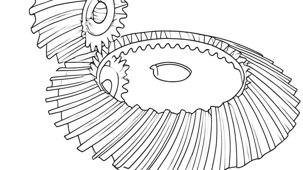
Spiral bevel gear is critical components in mechanical transmission systems due to their high load-bearing capacity, smooth operation, and low noise. Traditional machining methods, such as cutting, compromise material utilization and disrupt the integrity of metal flow lines. Rolling forming, a near-net-shape process, offers advantages like improved material efficiency, enhanced mechanical properties, and reduced production costs. However, defects such as tooth misalignment, folding, and “rabbit ear” formations persist in spiral bevel gear rolling, primarily due to mismatched rotational speeds between the forming wheel and die wheel. This study addresses these challenges by proposing a novel rolling process that ensures equal arc lengths at any moment during rolling, optimizing parameters, and analyzing metal flow line evolution.

Theoretical Analysis of Spiral Bevel Gear Rolling
Causes of Tooth Misalignment
Tooth misalignment arises from inconsistent pitch matching between the forming wheel and die wheel during rolling. The root cause lies in the mismatch of rotational angles when the same number of teeth engage. This discrepancy creates unequal arc lengths, leading to folding defects and uneven load distribution. The relationship between rotational speeds and arc lengths can be expressed as:r1ω1=r2ω2r1ω1=r2ω2
where r1r1 and r2r2 are the pitch radii of the forming and die wheels, and ω1ω1 and ω2ω2 are their angular velocities. Ensuring r1θ1=r2θ2r1θ1=r2θ2 (equal arc lengths) eliminates misalignment.
Design of Variable-Roll-Ratio Die Wheels
A multi-die system with variable tooth numbers adapts to the forming wheel’s dynamically changing pitch radius. The die wheel’s rotational speed is adjusted based on the forming wheel’s instantaneous pitch radius:ω2i=r1ir2ω1ω2i=r2r1iω1
where r1ir1i is the forming wheel’s pitch radius at the ii-th stage. This approach ensures continuous pitch matching and minimizes cumulative errors.
Feasibility Validation via Numerical Simulation
Finite Element Model Setup
Using Deform-3D software, a finite element model was established with the following parameters:
- Material: 20CrMnTi steel
- Heating: Induction heating to 900°C
- Friction: 0.1 (die-workpiece), 0.8 (workpiece-drive shaft)
- Rotation Speed: 30 RPM (forming wheel)
Simulation Results
- Tooth Folding Reduction: The new process reduced folding defects by 98% compared to single-die rolling.
- Load Reduction:
- Torque decreased by 75%
- Axial force decreased by 75%
- Circumferential force decreased by 50%
- Volume Loss: End-volume loss reduced by 5.13% due to controlled axial forces.
Table 1: Comparison of Rolling Processes
| Parameter | Single-Die Rolling | Variable-Die Rolling |
|---|---|---|
| Tooth Folding Defects | 921 triangles | 18 triangles |
| Torque (N·m) | 15,000,000 | 3,750,000 |
| Axial Force (N) | 35,000 | 8,750 |
Optimization of Process Parameters
A single-factor optimization method was employed to analyze critical parameters affecting forming quality. The “rabbit ear” defect evaluation index (pp) was defined as:p=h2−h1h1×100%p=h1h2−h1×100%
where h1h1 is the effective tooth height and h2h2 is the actual height.
Key Findings:
- Groove Depth: Increasing groove depth from 2 mm to 4 mm raised pp from 4.75% to 4.94% due to enhanced material accommodation.
- Die Tip Fillet Radius: Optimal fillet radius was 0.5 mm, balancing stress concentration and material flow.
- Friction Factor: Higher friction (0.3) reduced pp to 3.99% by restraining lateral material flow.
- Temperature: At 1000°C, pp dropped to 3.3% owing to improved plasticity.
- Forming Wheel Speed: Higher speeds (50 RPM) increased pp to 5.85% due to rapid deformation.
Table 2: Single-Factor Optimization Results
| Parameter | Optimal Value | pp Reduction |
|---|---|---|
| Groove Depth | 2 mm | 4.75% → 4.35% |
| Die Tip Fillet Radius | 0.5 mm | 4.75% → 4.45% |
| Friction Factor | 0.3 | 4.75% → 3.99% |
| Temperature | 1000°C | 4.35% → 3.3% |
Metal Flow Line Evolution in Spiral Bevel Gear Rolling
Characteristics of Metal Flow Lines
Metal flow lines exhibit directional fiber-like patterns aligned with plastic deformation. Key observations include:
- Tooth Root Densification: Flow lines concentrated at tooth roots, enhancing bending fatigue resistance.
- Layered Distribution: Flow lines near tooth surfaces bent toward the root, forming a gradient structure.
- Defect Suppression: No fractures, vortices, or exposed flow lines were observed in variable-die rolling.
Relationship Between Forces and Flow Lines
- Circumferential Force: Governed material densification at tooth roots. Higher forces intensified flow line curvature.
- Axial Force: Caused end-volume loss and spiral-oriented flow lines.
- Radial Force: Induced layered flow line distribution near tooth surfaces.
Table 3: Force Components and Flow Line Effects
| Force Type | Magnitude Range (N) | Flow Line Impact |
|---|---|---|
| Circumferential | 20,000–40,000 | Root densification |
| Axial | 5,000–15,000 | Spiral orientation, end loss |
| Radial | 10,000–30,000 | Layered surface distribution |
Tooth Surface Folding Mechanism
Folding defects originated from reconstructed tooth profiles during misaligned rolling. Key factors included:
- Material Overlap: Secondary material flow over previously formed surfaces.
- Asymmetric Friction: Uneven material velocity between active and passive tooth sides.
The folding depth (dfdf) correlated with axial force (FaFa) and friction (μμ):df∝Fa⋅μr1⋅ω1df∝r1⋅ω1Fa⋅μ
Conclusions and Future Work
Conclusions
- A variable-die rolling process ensured pitch matching, reducing tooth folding by 98% and torque by 75%.
- Optimal parameters included 1000°C forming temperature, 0.3 friction factor, and 2 mm groove depth.
- Metal flow lines exhibited root densification and gradient structures, enhancing mechanical properties.
Future Directions
- Develop a unified theoretical model for initial billet volume and die-wheel geometry.
- Explore orthogonal experiments for multi-parameter optimization.
- Implement meshless methods for efficient deformation analysis.
This study advances spiral bevel gear manufacturing by integrating process optimization with metal flow control, paving the way for high-performance gear production.
