
Abstract: This article focuses on the optimization of cylindrical spur gear parametric modeling in SolidWorks. It begins with an introduction to the importance of accurate gear modeling in mechanical transmission systems, highlighting the widespread use of spur gear. The challenges in existing SolidWorks-based gear modeling methods are identified, such as inaccurate tooth profiles and difficulties in parameter modification. The article then delves into the details of the optimization process, including the derivation and application of the involute equation, parameterization techniques, and the use of conditional functions for handling different numbers of teeth. The results show that the optimized method significantly improves the accuracy and efficiency of spur gear modeling, providing a more reliable and flexible approach for spur gear design in SolidWorks.
1. Introduction
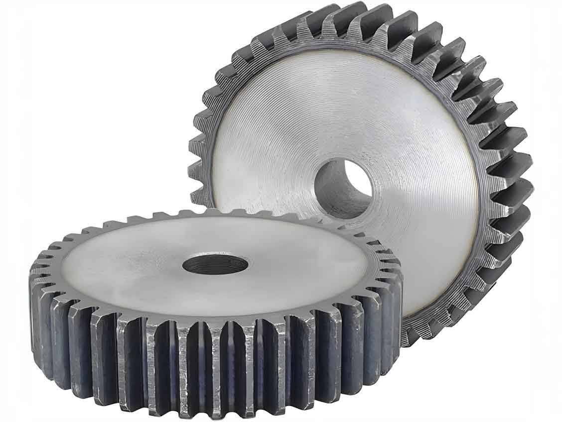
In mechanical transmission systems, gears play a crucial role, and among them, the cylindrical spur gear is widely used due to its advantages such as a wide range of circumferential speeds and power, long service life, precise and stable transmission ratio, and high efficiency. In practical applications, high machining and assembly accuracies are required for gear mechanisms. In scenarios such as finite element analysis and motion simulation, where high precision of the structure and model is essential, an accurate spur gear model is vital. Additionally, reducing the variety of software used in model design can enhance the efficiency of engineers.
Existing methods for creating spur gear models in SolidWorks have several drawbacks. Some methods, like using the Toolbox plugin or replacing the involute with arcs or spline curves, result in non-standard involute tooth profiles and low gear accuracy, which is unfavorable for subsequent mechanical and simulation analyses. Other methods that use equation-driven approaches to draw the involute may produce gears that are not symmetric about the x or y-axis, causing inconvenience in assembly. Methods relying on external plugins like Madi, GearTrax, or CAXA require re-drawing the gear when the gear size changes, rather than allowing direct parameter modification in SolidWorks.
2. Involute Equation
2.1 Basic Involute Equation
The accurate drawing of the involute is fundamental to the precise modeling of cylindrical gear. The involute is formed when a straight line rolls purely on a fixed circle. The parametric equation of the involute is given by:
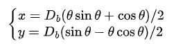
where Db is the base circle diameter and θ is the unwrapping angle.
2.2 Optimization of the Involute Equation
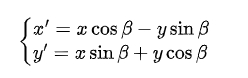
The spur gear generated using the basic involute equation may not be symmetric about the x-axis. To address this, the involute needs to be rotated about the origin. By analyzing the rotation of coordinates, we can obtain the relationship between the original coordinates (x,y) and the rotated coordinates (x’,y’) as follows:
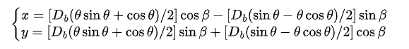
The rotation angle β can be calculated based on the properties of the involute and the spur gear geometry. The final optimized polar coordinate parametric equation of the involute is:
3. Cylindrical Spur Gear Parametric Modeling
3.1 Basic Parameters
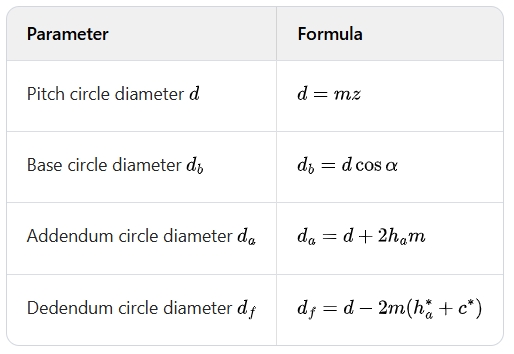
The standard parameters of a cylindrical spur gear include the module , pressure angle , number of teeth , clearance coefficient , and addendum coefficient . The basic dimensions of the spur gear can be calculated as follows:
3.2 Creating Global Variables
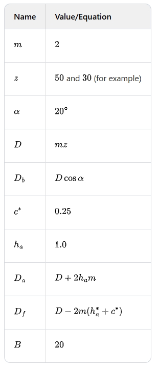
In the SolidWorks work interface, global variables such as , , , (pitch circle diameter), (base circle diameter), , , (dedendum circle diameter), (another related diameter), and (gear width) are defined in the “Equations” – “Manage Equations” option. The values and corresponding formulas are entered as shown in the following example:
3.3 Drawing Circles and Involute Sketches
- Drawing Circles: The addendum circle, pitch circle, dedendum circle, and base circle sketches are drawn with the origin as the center, from large to small. The sizes are associated with the global variables using “Smart Dimension” and selecting the appropriate global variable for each circle.
- Constructing Involute: A new variable (rotation angle) is added in the “Equations” – “Global Variables”. The value of is calculated based on spur gear parameters. The involute is drawn using the “Equation Driven Curve” option with the parameter equation entered as described in the previous section. The range of the unwrapping angle is controlled by setting parameters and .
3.4 Creating Gear Solid Model
- Generating Blank Model: The spur gear blank is generated using the “Feature” – “Extrude Boss” command, with the addendum circle as the contour and the spur gear width as the extrusion length, achieving parameterized association of the spur gear thickness.
- Cutting a Single Tooth Slot: A sketch is drawn on one side of the spur gear blank, including the dedendum circle, addendum circle, and involute. The intersections of the dedendum and addendum circles with the X-axis are connected with a straight line. The circles are trimmed to form a half-closed tooth slot profile. The profile is then extruded and removed using the “Feature” – “Extrude Cut” command with the length . The feature is mirrored about the “Top View” reference plane to complete the cutting of a single tooth slot. A fillet is added to the tooth root with a radius .
- Arraying to Complete Tooth Profile Modeling: The cut tooth profile is arrayed circumferentially with the number of teeth as the array quantity, achieving the equation association of the number of teeth.
4. Parameter Compression for Modeling
When the base circle is larger than the dedendum circle (), for a certain number of teeth (), the starting point of the involute is outside the dedendum circle. Directly modifying the parameters in such cases may lead to model reconstruction failure. To address this, conditional control of feature compression is used.
4.1 IF Function for Compression Control
In SolidWorks, the Visual Basic If function can be used to conditionally control model variables. The basic usage is . For example, means when and when . In the context of spur gear modeling, we can use to control the compression of features depending on the number of teeth.
4.2 Creating the Final Gear Model
- Compressing the Original Model: The “Equations” are opened, and in the “Feature” – “Name” section, features like “Cut”, “Mirror”, “Array”, and “Fillet” are selected. The “Value/Equation” is set as , and the number of teeth in the global variables is modified, for example, to . This compresses the original model.
- Modeling for Small Number of Teeth: The involute, addendum circle, and dedendum circle are referenced and trimmed to form an unclosed figure. A straight line is drawn to connect the starting point of the involute and the dedendum circle, and a geometric constraint is added to make the line tangent to the involute, forming a closed figure. Then, operations like cutting, mirroring, filleting, and arraying are performed to complete the modeling for a small number of teeth (). The new features are added to the “Equations” – “Feature” with the appropriate compression control based on the number of teeth.
5. Conclusion
The optimized method for spur gear parametric modeling in SolidWorks presented in this article offers several advantages. The model file can be saved as a template for future use. By modifying the global variables such as the module and number of teeth, the required gear model can be directly generated. The use of the involute’s parameter equation ensures the accuracy of spur gear. The generated gear is symmetric about the top view reference plane, facilitating assembly and finite element analysis. Moreover, a single model can be used to generate gears with any number of teeth, reducing errors when changing the number of teeth and improving efficiency. This method also provides a useful approach for the parametric modeling of components with multiple parameters, such as modified gears.