The transmission error and contact marks of helical gears can reflect the meshing performance of helical gear pairs. To investigate the impact of different tooth profile and tooth alignment modification parameters on the load bearing characteristics of the tooth surface, four modification coefficients for the driving wheel are set, as shown in the table. Conduct finite element analysis and finite element transient dynamic analysis on helical gear pairs, and compare the contact stress values and the maximum equivalent stress nephogram of the tooth surface under different modification parameters through simulation analysis.
| Case | Tooth profile modification coefficient amp | Tooth alignment modification coefficient ac |
| 1 | 0.00002 | 0.00002 |
| 2 | 0.00008 | 0.00002 |
| 3 | 0.00005 | 0.00003 |
| 4 | 0.00005 | 0.0001 |
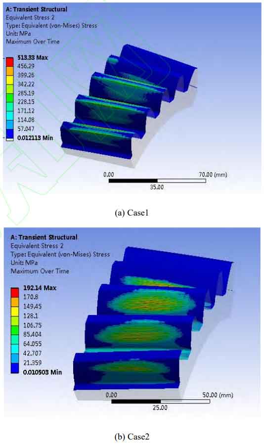
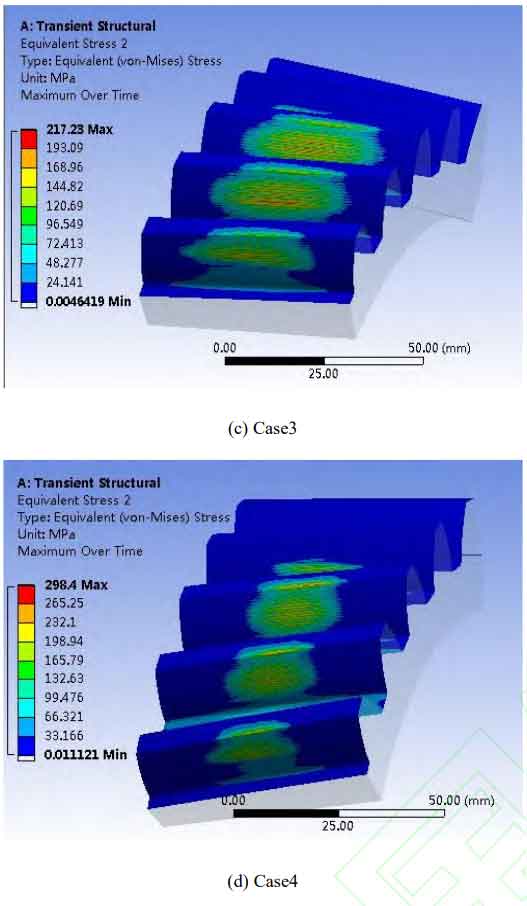
The maximum equivalent stress nephogram is shown in Figure 1. In case 1, the modification coefficient is small, and there is a large meshing interference phenomenon on the tooth surface. The maximum stress is concentrated at the top of the tooth, and the maximum equivalent stress value is 513.33MPa; The minimum maximum equivalent stress value of case 2 is 192.14MPa, which basically eliminates the phenomenon of meshing interference. The maximum stress occurs in the middle of the tooth surface, which proves that the tooth surface contact characteristics under this modification scheme are good, and the meshing interference amount is small, which can effectively reduce the problem of tooth tip interference of helical gears. Compared to case 3 and case 4, when the amount of tooth modification increases, the meshing area of the helical gear gradually concentrates in the middle of the tooth surface, and the contact mark becomes increasingly centered. When the tooth profile modification coefficient is too large, the force on the tooth surface will rapidly expand, and the instantaneous contact area will become smaller.
Add a Contact Tool to the solution result to define the second tooth surface of the driven gear as the contact tooth surface to observe the change trend of contact stress during the helical gear meshing cycle, to solve the range of contact stress amplitude changes on the tooth surface under different modification factors, as shown in Figure 2.
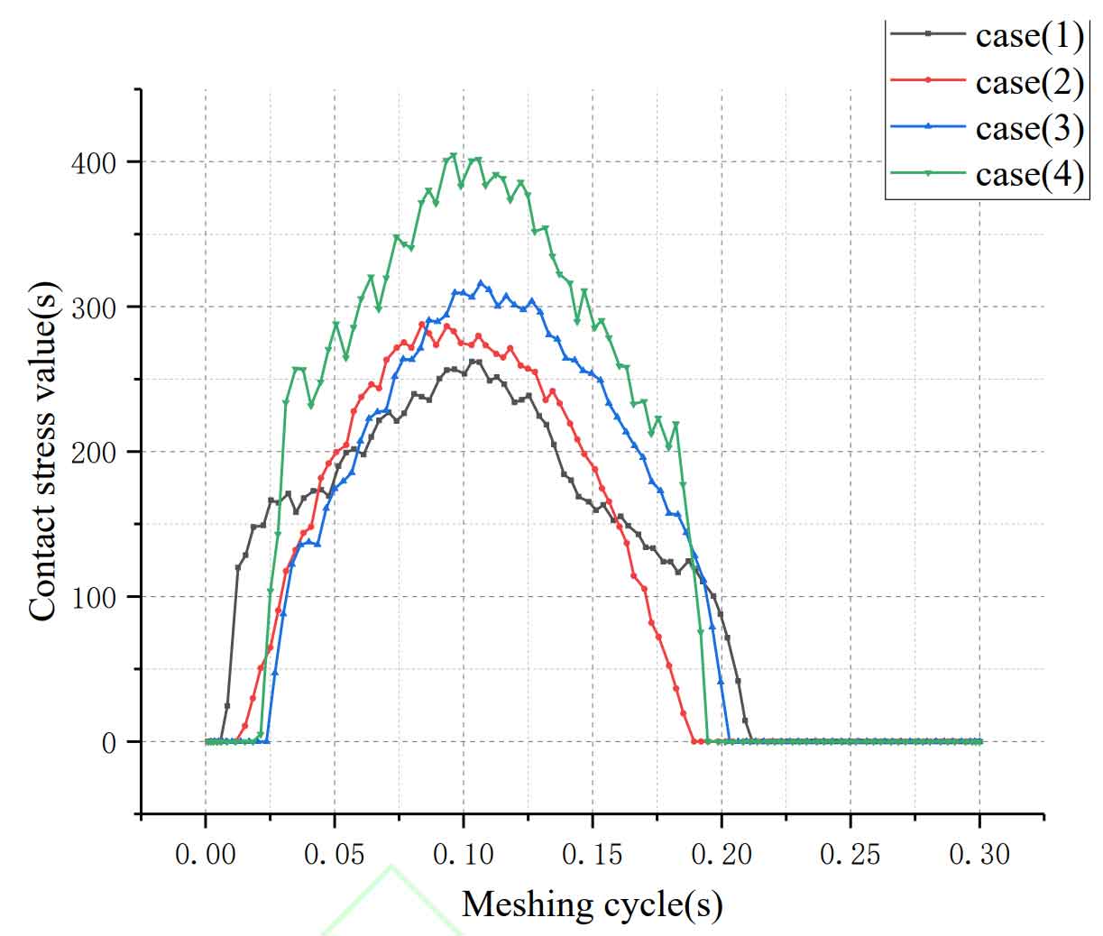
As can be seen from the figure, during the meshing cycle, the overall contact stress curve assumes a parabolic shape with an opening downward. The maximum contact stress values on the tooth surface from case 1 to case 4 are 262.11 MPa, 302.79 MPa, 315.96 MPa, and 404.53 MPa, respectively. When case 1 has a tooth profile modification coefficient of amp=0.0002 and a tooth alignment modification coefficient of ac=0.0002, the contact stress curve of the helical gear pair has a large opening and a small slope, indicating that the meshing overlap of the tooth surface is large, but there are small secondary stress peaks, which may be due to the small amount of tooth profile modification and the incomplete elimination of tooth tip meshing interference. The gradient of the contact stress curve from case 2 to case 4 gradually increases, and the amplitude of the contact stress increases sharply with the increase of the modification coefficient, which proves that the coincidence degree of the tooth surface decreases. However, with the increase of the tooth profile modification coefficient, there is no secondary peak phenomenon during the meshing cycle. This indicates that increasing the amount of tooth profile modification can effectively reduce the interference problem at the top of helical gears, reduce the load on the top of the teeth, eliminate the stress concentration at the top of the teeth, concentrate the load on the middle area of the teeth, and improve the meshing condition.
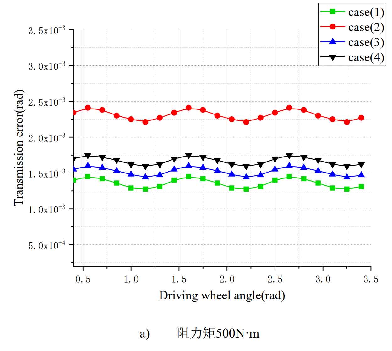
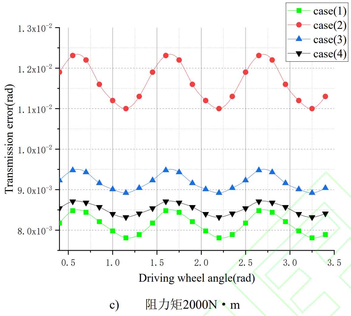
In order to better understand the transmission error changes of helical gear pairs under different working conditions, three types of torques, namely, 500 N · m, 1000 N · m, and 2000 N · m, are set for helical gear pairs under different modification cases. Maintain the rotational speed of 20rad/s unchanged. Figure 3 shows the transmission error variation of helical gear pairs under light, medium, and heavy load conditions under four types of modification coefficient cases. From the figure, it can be seen that the transmission error increases with the increase of resistance torque, and the transmission error curve roughly fluctuates in a sinusoidal curve.
When the load is 1000 N · m and the modification coefficients are amp=0.0005 and ac=0.0003, the average transmission error is 6.59 × 10^-3rad; When the modification coefficients are amp=0.0005 and ac=0.0001, the average transmission error is 6.34 × 10^-3rad。
When the load is 2000 N · m and the modification coefficients are amp=0.0005 and ac=0.0003, the average transmission error is 9.18 × 10⁻³rad; When the modification coefficients are amp=0.0005 and ac=0.0001, the average transmission error is 8.52 × 10⁻³rad。 It can be seen that the transmission error of case 3 is greater than that of case 4. When the modification coefficient is amp=0.0002 and ac=0.0002, the transmission error is the smallest under three loads, respectively 1.45 × 10^-3rad 、 5.56 × 10^-3rad 、 8.14 × 10^-3rad ; When the modification coefficient is amp=0.0008 and ac=0.0002, the transmission error is the largest, respectively 2.31 × 10^-3rad、7.24 × 10^-3rad、11.64 × 10^-3rad。 It can be seen that under the same load, the increase in the tooth profile modification coefficient has a greater impact on the transmission error amplitude.
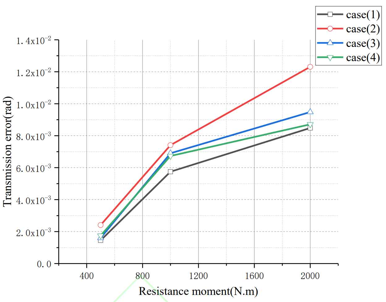
The transmission error amplitude under different resistance moments is shown in Figure 4. When the load is 500 N · m and the modification coefficients are amp=0.0002 and ac=0.0002, the transmission error amplitude is the smallest, which is 1.45 × 10^-3rad; When the modification coefficients are amp=0.0002 and ac=0.0002 at 1000N · m, the transmission error amplitude is the smallest, which is 5.75 × 10^-3rad; When the modification coefficients are amp=0.0002 and ac=0.0002 at 2000N · m, the transmission error amplitude is the smallest, which is 8.48 × 10^-3rad。 Under the three resistance moments, the error amplitude of case 1 is the smallest and the variation trend is relatively stable; Case 2 has the largest transmission error amplitude. It can be seen that under different resistance moments, the modification coefficient is different, and the transmission error amplitude changes in different forms. When the gear pair is lightly loaded, the modification coefficient has a small impact on the transmission error amplitude; However, as the load increases, the amplitude change tends to increase. The amplitude of the transmission error of the gear pair during loading can reflect the vibration situation during the transmission process. The larger the amplitude, the greater the vibration, and the greater the noise generated. Therefore, it is necessary to reasonably select the modification coefficient according to different working conditions to reduce the impact of transmission error of helical gear pairs in order to obtain ideal meshing transmission characteristics.
Taking a pair of helical gear pairs as the research object, the modified tooth surface modeling was conducted in Mathematica, and the load carrying capacity of the modified helical gear pair was simulated and analyzed using Workbench. The tooth surface analysis results of standard helical gear pairs without modification under load conditions were compared, and different tooth profile and tooth alignment modification coefficients were changed to solve the transmission error and contact marks of the helical gear pair under different modification coefficients, Obtaining the tooth surface contact stress and maximum equivalent stress nephogram under different modification coefficients, analyzing the influence of modification parameters on the tooth surface contact characteristics, and setting various loads to investigate the amplitude of transmission error of helical gear pairs. The results show that the tooth profile modification has a significant impact on the transmission error amplitude, and the tooth alignment modification has a significant impact on the tooth surface contact area. Under different loads, different modification coefficients have different effects on the transmission characteristics of helical gear pairs, and their transmission error amplitude variation trends are also different. To obtain the required meshing performance of helical gears, it is necessary to select the appropriate modification coefficient based on actual working conditions, which provides a theoretical basis for subsequent research on the dynamics of modified helical gears.

