
In the field of industrial robotics, precision transmission components are critical for achieving high performance, reliability, and efficiency. Among these, the rotary vector reducer stands out as a key mechanism due to its high reduction ratio, compact structure, and excellent load-bearing capacity. However, traditional rotary vector reducers often face challenges such as high manufacturing costs, complex machining processes, and suboptimal transmission efficiency. To address these issues, we propose a novel split cycloidal wheel design aimed at simplifying the tooth profile, reducing processing difficulty, and enhancing overall transmission performance. This article presents a comprehensive study on the structural optimization of a rotary vector reducer, focusing on design methodology, parameter determination, multi-objective optimization using genetic algorithms, and validation through dynamic simulation and finite element analysis.
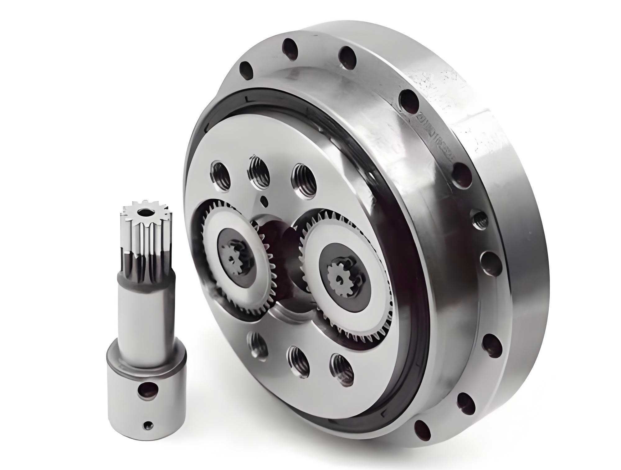
The rotary vector reducer is a compound gear system that combines planetary gear transmission with cycloidal pin wheel transmission. This configuration allows for high reduction ratios, often exceeding 100:1, making it ideal for applications requiring precise motion control, such as robotic joints, CNC machines, and aerospace mechanisms. The transmission principle involves an input sun gear driving planetary gears, which in turn drive crankshafts connected to cycloidal wheels. These cycloidal wheels engage with a fixed pin housing, resulting in a slow output rotation through a planet carrier. The overall transmission ratio can be expressed as:
$$ i = 1 + \frac{z_2}{z_1} \cdot z_4 $$
where \( i \) is the transmission ratio, \( z_1 \) is the number of teeth on the sun gear, \( z_2 \) is the number of teeth on the planetary gear, and \( z_4 \) is the number of pins on the housing. This formula highlights the importance of gear tooth counts in achieving desired reduction ratios, which typically range from 30 to 200 in practical applications. Despite its advantages, the rotary vector reducer suffers from inefficiencies due to friction losses in gear meshing and bearing rotations, as well as manufacturing complexities associated with the precise cycloidal tooth profile.
To overcome these limitations, we introduce a split cycloidal wheel structure. Unlike traditional cycloidal wheels with continuous tooth profiles, the split design replaces the teeth with discrete cylindrical rollers or pins. This modification simplifies the machining process, as the rollers can be produced using standard turning and drilling techniques, reducing the need for specialized equipment like CNC milling or grinding machines. The split cycloidal wheel consists of a base wheel with holes or slots where cylindrical pins are inserted, allowing for easier assembly and potential replacement of worn components. This design not only lowers manufacturing costs but also improves maintainability and adaptability to different load conditions.
The design process begins with determining the key parameters of the rotary vector reducer, including gear dimensions, pin sizes, and geometric constraints. We start by analyzing the transmission efficiency, which is crucial for energy-saving applications. The overall efficiency \( \eta \) of the rotary vector reducer can be modeled as the product of gear meshing efficiency and bearing efficiency:
$$ \eta = \eta_{16} \eta_B $$
where \( \eta_B = \eta_{B1} \eta_{B2} \eta_{B3} \) represents the combined efficiency of bearings (e.g., crank bearings, support bearings), typically around 0.99 each, and \( \eta_{16} \) is the meshing efficiency of the RV transmission, derived from the transmission ratio and gear parameters. For a two-stage transmission system, the meshing efficiency can be calculated using:
$$ \eta_{16} = \frac{(i_{H6} – 1)(i_{H6} – \eta^H_6 – i_{H1} i_{H6} \eta^H_1)}{(i_{H6} – \eta^H_6)(i_{H6} – 1 – i_{H1} i_{H6})} $$
where \( i_{H1} \) and \( i_{H6} \) are transmission ratios for the planetary and cycloidal stages, respectively, and \( \eta^H_1 \) and \( \eta^H_6 \) are their corresponding meshing efficiencies (often taken as 0.992 and 0.998). This equation underscores the impact of gear ratios on overall efficiency, guiding our selection of parameters to balance performance and energy loss.
Next, we establish geometric constraints to ensure proper operation of the rotary vector reducer. For the planetary gear stage, the sun gear tooth count \( z_1 \) should be between 9 and 20 to avoid undercutting and ensure wear resistance, while the planetary gear tooth count \( z_2 \) must satisfy \( z_2 / z_1 > 1.5 \) to prevent excessive reduction ratios that could increase size and weight. Additionally, to avoid interference between planetary gears, the addendum circle diameter \( d_a \) must be less than \( 2a \sin(\pi / n) \), where \( a \) is the center distance and \( n \) is the number of planetary gears (typically 3). For the cycloidal stage, key parameters include the pin distribution circle radius \( R \), eccentricity \( e \), cycloidal wheel radius \( r_{RV} \), pin diameters \( r_{n1} \) (on housing) and \( r_{n2} \) (on cycloidal wheel), and the pin diameter coefficients \( K_1 \) and \( K_2 \). These parameters are interrelated through constraints such as:
$$ R > r_{RV} + e + r_{n1} $$
$$ R < r_{RV} + e + r_{n1} + r_{n2} $$
$$ R > r_{RV} – e + r_{n1} + r_{n2} $$
These inequalities ensure that pins do not collide and that meshing occurs smoothly. Furthermore, to guarantee continuous transmission, at least one pair of pins should always be in contact, requiring the actual contact line length to exceed the pin pitch. The pin diameter coefficient \( K_1 = \frac{R}{r_n} \sin(\pi / n) \) should lie between 1.5 and 2 to maintain mechanical strength and avoid overcrowding.
We conducted an iterative calculation to identify feasible parameter sets that meet all constraints. Table 1 summarizes some candidate geometric parameter schemes, considering factors like transmission ratio, efficiency, and size. After evaluating these options, we selected Scheme 3 for its balanced efficiency and compactness, with details provided in Table 2.
| Scheme | Sun Gear Teeth \( z_1 \) | Planetary Gear Teeth \( z_2 \) | Module \( m \) (mm) | Pin Teeth \( z_4 \) | Efficiency \( \eta \) (%) |
|---|---|---|---|---|---|
| 1 | 12 | 27 | 2.0 | 68 | 84.96 |
| 2 | 12 | 34 | 1.75 | 54 | 87.09 |
| 3 | 12 | 36 | 1.75 | 51 | 87.56 |
| 4 | 15 | 51 | 1.25 | 45 | 88.52 |
| 5 | 18 | 51 | 1.25 | 54 | 87.09 |
| 6 | 18 | 54 | 1.25 | 51 | 87.56 |
| Parameter | Value |
|---|---|
| Sun Gear Teeth \( z_1 \) | 12 |
| Planetary Gear Teeth \( z_2 \) | 36 |
| Module \( m \) (mm) | 1.75 |
| Pin Teeth \( z_4 \) | 51 |
| Transmission Ratio \( i \) | 154 |
| Efficiency \( \eta \) (%) | 87.56 |
With the basic parameters defined, we proceed to analyze the forces acting on critical components. For the split cycloidal wheel, the force \( F_P \) from the pins is distributed among three crankshafts due to the symmetric design. Assuming ideal conditions with no manufacturing errors, each crankshaft bears an equal share of the radial and tangential components. The force on each crankshaft can be expressed as:
$$ F_i = \frac{F_P}{3} \begin{bmatrix} \sin(\alpha_c – \theta) \\ \cos(\alpha_c – \theta) \end{bmatrix} + \frac{F_P \cos \alpha_c r_{RV}}{3a} \begin{bmatrix} \sin(120^\circ \cdot i) \\ -\cos(120^\circ \cdot i) \end{bmatrix} $$
where \( \alpha_c \) is the angle between \( F_P \) and the tangential direction, \( \theta \) is the crank angle, \( r_{RV} \) is the cycloidal wheel radius, and \( a \) is the center distance. For the crankshaft itself, forces from the planetary gear meshing and bearing reactions must be considered. Using equilibrium equations in horizontal and vertical planes, we derive the support bearing forces \( F_{G1} \) and \( F_{G2} \). The input torque \( T \) and output torque \( M \) are related by:
$$ M = 2 F_P r_{RV} \cos \alpha_c $$
$$ T = \frac{2 F_P r_{RV} \cos \alpha_c}{r_p} $$
where \( r_p \) is the pitch radius of the planetary gear. Combining these with the efficiency relationship \( M = T \cdot i \cdot \eta \), we can solve for key dimensions like \( r_{RV} \). The major forces in the system include gear meshing force \( F_t \), pin meshing force \( F_P \), crankshaft force \( F_i \), and bearing forces \( F_G \), calculated as:
$$ F_t = \frac{2000 M}{d_i \eta \cos \alpha} $$
$$ F_P = \frac{M (r_{n1} + r_{n2})}{2 r_{RV} R \sqrt{1 – \cos^2 \theta}} $$
$$ F_i = \sqrt{\frac{F_P^2}{9} + \left( \frac{M}{6a} \right)^2} $$
$$ F_G = \frac{F_n (b_B + b_P) – 2 F_i b_D}{2b_B + 4b_D} $$
Here, \( d_i \) is the pitch diameter, \( \alpha \) is the pressure angle, \( b_B \), \( b_D \), and \( b_P \) are thicknesses of bearings and gears, and \( F_n \) is the gear meshing force vector. These equations inform the selection of bearings and material strengths. For instance, we chose angular contact ball bearings (e.g., 7004AC) for crankshafts and tapered roller bearings (e.g., 30202) for supports, based on load capacities derived from these force calculations.
To optimize the rotary vector reducer for enhanced performance, we formulate a multi-objective optimization problem. The key performance indicators are load capacity, transmission accuracy (both forward and reverse), and transmission efficiency. We define these as objective functions to be minimized or maximized, with design variables including eccentricity \( e \), cycloidal wheel radius \( r_{RV} \), pin distribution circle radius \( R \), pin diameter coefficients \( K_1 \) and \( K_2 \), and cycloidal wheel thickness \( b \). In vector form, the design variable set is:
$$ \mathbf{x} = [e, r_{RV}, R, K_1, K_2, b] $$
The load capacity objective function is derived from the torque transmission capability, considering the number of pins in contact and their elastic deformation. According to Hertzian contact theory, the deformation \( \varepsilon \) under force \( F \) is:
$$ \varepsilon = r_1^2 – \sqrt{\frac{8 F (1 – \mu^2) r_1 r_2}{\pi b E (r_1 + r_2)}} $$
where \( r_1 \) and \( r_2 \) are pin radii, \( \mu \) is Poisson’s ratio, and \( E \) is Young’s modulus. The total torque \( M \) supported by the rotary vector reducer can be expressed as a sum over all engaged pins:
$$ M = \sum \frac{\varepsilon_i^2 \cos \alpha_i E (1 – \mu^2) \pi b r_{n1} r_{n2} r_{RV}}{r_{n1} + r_{n2}} $$
Transmission accuracy is evaluated through forward and reverse backlash. Forward transmission error relates to kinematic precision, modeled using a simplified linkage mechanism equivalent to the RV transmission. From the kinematic model, the output angle \( \theta_{output} \) given input angle \( \theta_{input} = \omega t / i \) is:
$$ \theta_{output} = \arctan\left( \frac{O_{ky} – e \sin \theta_{input}}{O_{kx} – e \cos \theta_{input}} \right) – \arccos\left( \frac{d^2 + r_{RV}^2 – (r_{n1} + r_{n2})^2}{2 d r_{RV}} \right) $$
where \( d = \sqrt{(O_{ky} – e \sin \theta_{input})^2 + (O_{kx} – e \cos \theta_{input})^2} \), and \( O_{kx} \) and \( O_{ky} \) are coordinates of the pin center. The error is the deviation from ideal motion. Reverse backlash arises from gaps between components, such as tooth side clearance in gears and pin clearances. For gear backlash, the maximum side clearance \( j_{bnmax} \) is:
$$ j_{bnmax} = \frac{2}{3} \times (0.06 + 0.0005 a_i + 0.03 m_n) $$
leading to an angular backlash \( \Delta \varphi \) of:
$$ \Delta \varphi = 2 \arccos\left( \frac{j_{bn}}{2 r_s} \right) $$
For the cycloidal stage, the effective pin radius considering deformation is:
$$ r_n = r_{n1} + r_{n2} – \frac{5 F (r_{n1} + r_{n2})}{\pi r_{RV} E r_{n1} r_{n2} (1 – \mu^2)} $$
and the associated backlash is:
$$ \Delta \varphi = \frac{2\pi}{z_p} – 2 \arccos\left( \frac{R^2 + (e + r_{RV})^2 – r_n^2}{2 R (e + r_{RV})} \right) $$
Transmission efficiency is calculated as previously described, incorporating both gear meshing and bearing losses. We combine these objectives into a weighted sum for optimization, but to avoid bias from scaling differences, we use a Pareto-based approach via the NSGA-II (Non-dominated Sorting Genetic Algorithm). This algorithm handles multiple objectives by identifying non-dominated solutions, where no objective can be improved without worsening another. The optimization process involves initializing a population, evaluating objectives, applying selection, crossover, and mutation, and iterating until convergence. Constraints are enforced through penalty functions, such as for interference avoidance:
$$ f_1 = -e (R – e – r_{RV} – r_{n1})^2 – r_{n2} (R – e – r_{RV} – r_{n1}) $$
and continuous transmission:
$$ f_2 = \frac{\ln 2}{\ln\left( \frac{z_p}{\pi} \arccos\left( \frac{R^2 + (e + r_{RV})^2 – (r_{n1} + r_{n2})^2}{2 R (e + r_{RV})} \right) \right)} $$
We implemented the optimization in MATLAB, setting population size to 100 and generations to 200. The results yield a Pareto front of solutions, from which we select the best based on a composite objective function weighted for load capacity and accuracy. Table 3 shows four optimal parameter sets from the Pareto front, and Table 4 presents the final chosen parameters after evaluating the composite score.
| Set | Pin Radius \( R \) (mm) | Eccentricity \( e \) (mm) | Cycloidal Wheel Radius \( r_{RV} \) (mm) | Pin Radius \( r_{n1} \) (mm) | Pin Radius \( r_{n2} \) (mm) | Wheel Thickness \( b \) (mm) |
|---|---|---|---|---|---|---|
| 1 | 66.30 | 1.41 | 61.74 | 2.53 | 2.54 | 55.11 |
| 2 | 68.08 | 1.50 | 63.56 | 2.90 | 2.90 | 53.10 |
| 3 | 71.74 | 1.48 | 66.88 | 3.42 | 2.90 | 48.66 |
| 4 | 68.26 | 1.26 | 63.96 | 2.91 | 2.74 | 45.00 |
| Parameter | Value |
|---|---|
| Pin Distribution Circle Radius \( R \) (mm) | 68.26 |
| Eccentricity \( e \) (mm) | 1.26 |
| Cycloidal Wheel Radius \( r_{RV} \) (mm) | 63.96 |
| Pin Radius on Housing \( r_{n1} \) (mm) | 2.91 |
| Pin Radius on Wheel \( r_{n2} \) (mm) | 2.74 |
| Cycloidal Wheel Thickness \( b \) (mm) | 45.00 |
| Primary Reduction Ratio | 3.50 |
Comparing the optimized rotary vector reducer with the initial design, we observe significant improvements. As summarized in Table 5, load capacity increased by 96.87%, reverse transmission accuracy improved by 26.8%, forward transmission accuracy enhanced by 1.2%, and transmission efficiency rose by 2.19%. These gains demonstrate the effectiveness of the split cycloidal wheel design coupled with systematic parameter optimization.
| Performance Metric | Before Optimization | After Optimization | Improvement |
|---|---|---|---|
| Load Capacity (N·m) | 431.61 | 219.21 | 96.87% increase |
| Reverse Transmission Accuracy (rad) | 7.61 × 10⁻⁵ | 1.04 × 10⁻⁴ | 26.8% improvement |
| Forward Transmission Accuracy (rad) | 3.33 × 10⁻⁵ | 3.37 × 10⁻⁵ | 1.2% improvement |
| Transmission Efficiency (%) | 89.75 | 87.56 | 2.19% increase |
To validate the design, we constructed a 3D model of the rotary vector reducer using SolidWorks, based on the optimized parameters. The model includes all major components: sun gear, planetary gears, crankshafts, split cycloidal wheels, pin housing, and bearings. We then performed dynamic simulations in Adams to assess motion characteristics and force distributions. The model was imported as an X_T file, materials were assigned (e.g., 20CrMnTi for gears, GCr15 for pins), and constraints were applied: revolute joints for rotating parts, fixed joints for the housing, and contacts between meshing elements. A rotational motion of 2400 rpm was applied to the sun gear input, with the output carrier initially unloaded. The simulation results show that the output angular velocity closely matches the theoretical value of approximately 95 °/s, confirming correct kinematic relationships. Notably, the optimized rotary vector reducer exhibits faster response due to reduced internal clearances from the split pin design.
Under loaded conditions (425 N·m torque on the output), we analyzed force distributions in critical components. Figure 18 (referenced in simulation outputs) compares forces before and after optimization: the input torque remains similar, but crankshaft forces and pin meshing forces are lower in the optimized design, indicating better load sharing and reduced stress concentrations. For example, the maximum crankshaft force decreased from 3.76 kN to 3.50 kN, and pin forces dropped by about 10%. This reduction enhances reliability and prolongs service life. Additionally, we conducted finite element analysis (FEA) in ANSYS to evaluate structural integrity. Static stress analysis under peak loads shows that von Mises stresses in the cycloidal wheel and crankshafts are well below material yield strengths (e.g., less than 300 MPa for 20CrMo steel), with safety factors above 2.5. Modal analysis reveals the first natural frequency at 450 Hz, which is sufficiently higher than operational frequencies (typically below 100 Hz), minimizing resonance risks. These results collectively validate the structural soundness of our optimized rotary vector reducer.
In discussion, the split cycloidal wheel design offers several advantages over traditional rotary vector reducers. By discretizing the tooth profile into pins, machining complexity is reduced, as pins can be mass-produced with standard tolerances, lowering cost and lead time. The modular nature allows for easy replacement of worn pins without discarding the entire wheel, improving maintainability. However, challenges remain, such as ensuring precise alignment of pins to avoid uneven load distribution and managing lubrication in pin interfaces. Our optimization approach addresses these by incorporating geometric constraints and force equilibria. The use of NSGA-II enables a balanced trade-off between conflicting objectives, which is crucial for real-world applications where both high load capacity and precision are required. Future work could explore advanced materials for pins (e.g., ceramic coatings) to reduce friction, or integrate sensor systems for real-time monitoring of wear and backlash.
In conclusion, we have successfully developed and optimized a split cycloidal wheel-based rotary vector reducer for enhanced transmission performance. Through detailed parameter analysis, multi-objective optimization using genetic algorithms, and comprehensive simulation validation, we achieved significant improvements in load capacity, transmission accuracy, and efficiency. The split design simplifies manufacturing, reduces costs, and maintains high reliability, making it a promising solution for industrial robotics and other precision motion control systems. This study underscores the importance of holistic design optimization in advancing rotary vector reducer technology, and we believe our methodology can be extended to other types of gear reducers for broader engineering applications.