| Number | Factor/mm | Level 1 | Level 2 | Level 3 |
| A(a1) | Groove width | 0.2 | 0.3 | 0.4 |
| B(a2) | Lateral clearance | 0.2 | 0.07 | -0.03 |
| C(a3) | Small hole diameter | 4 | 6 | 8 |
The main influencing factors involved in the vibration damping structure include groove width, side clearance, and small hole diameter. For the level of these three influencing factors, the backlash of cylindrical gears is approximately 0 Select below 2 mm; The groove comprehensively considers the structural strength and technological conditions of the gear teeth, and each level is roughly equivalent. Three levels are selected as shown in Table 1. The orthogonal test table design is shown in Table 2.
| Serial Number | A/mm | B/mm | C/mm |
| 1 | 0.2 | 0.2 | 4 |
| 2 | 0.2 | 0.07 | 8 |
| 3 | 0.2 | -0.03 | 6 |
| 4 | 0.3 | 0.2 | 4 |
| 5 | 0.3 | 0.07 | 8 |
| 6 | 0.3 | -0.03 | 6 |
| 7 | 0.4 | 0.2 | 4 |
| 8 | 0.4 | 0.07 | 8 |
| 9 | 0.4 | -0.03 | 6 |
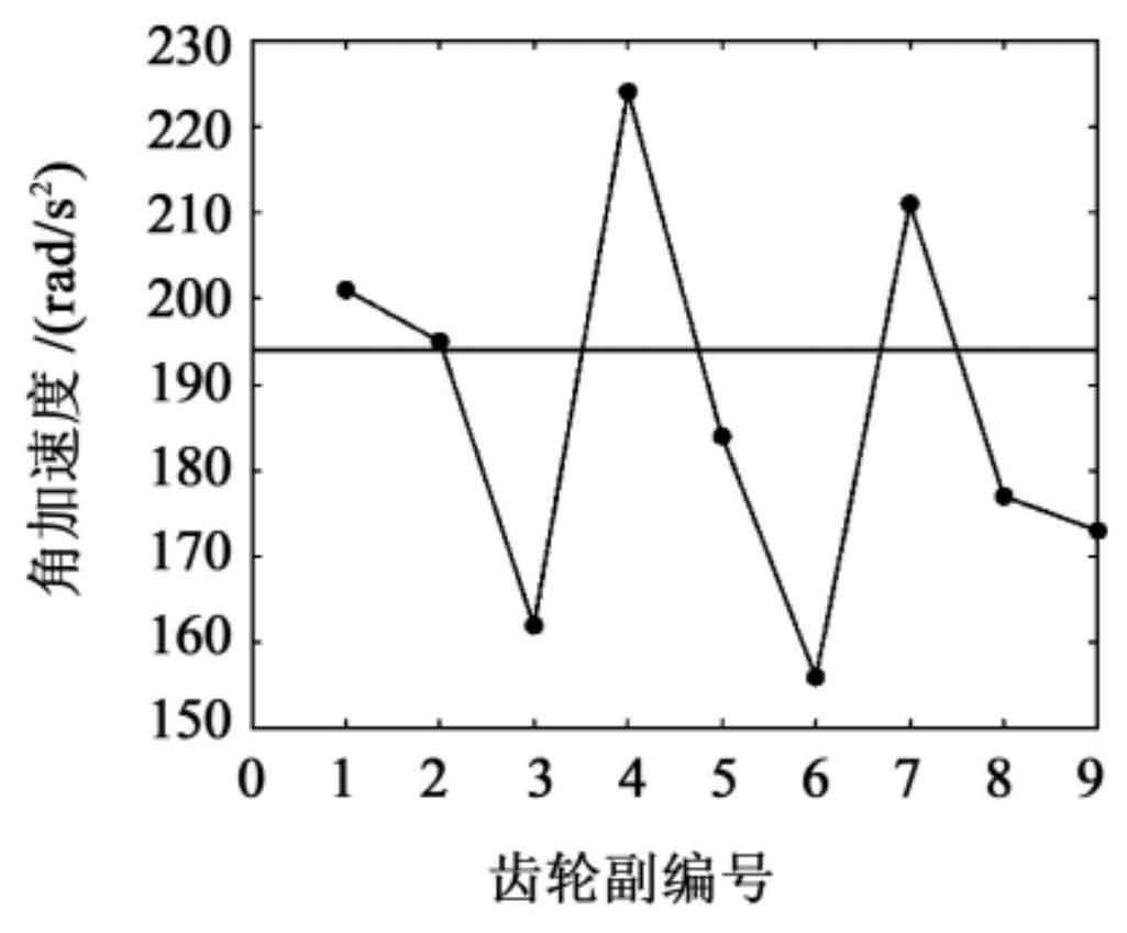
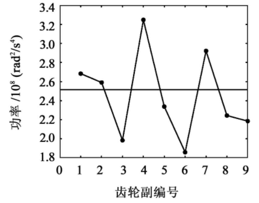
According to the simulation calculation process, perform angular acceleration simulation for the nine groups of tests shown in Table 2, and then perform Fourier transform and related power spectrum analysis. The test simulation results are shown in Table 3. From Table 3, it can be seen that the variation trend of the angular acceleration at the meshing frequency is consistent with the total power (energy) value of the power spectrum (comparison between Figure 1 and Figure 2). Therefore, either angular acceleration or total power can be selected as a measurement index to analyze the horizontal correlation of orthogonal test factors for cylindrical gears.
| Gear pair number | Angular acceleration (/rad/s ^ 2) | Total power (/rad ^ 2/s ^ 4) |
| 1 | 201 | 2.683×10^8 |
| 2 | 195 | 2.59×10^8 |
| 3 | 162 | 1.984×10^8 |
| 4 | 224 | 3.247 × 10^8 |
| 5 | 184 | 2.338 × 10^8 |
| 6 | 156 | 1.859 × 10^8 |
| 7 | 211 | 2.921 × 10^8 |
| 8 | 177 | 2.244 × 10^8 |
| 9 | 173 | 2.185 × 10^8 |
The horizontal lines shown in Figures 1 and 2 are the vibration acceleration data of the original structure cylindrical gear pair. From the figure, it can be seen that the structures in groups 3, 5, 6, 8, and 9 have significant vibration reduction effects, with the combination of parameters in group 6 having the most obvious vibration reduction effect.