
Introduction
Spur gears are among the most fundamental components in mechanical transmission systems, offering simplicity, reliability, and efficiency in power transfer. However, designing spur gears requires precise modeling of their involute tooth profiles, which can be time-consuming and error-prone if done manually. In this paper, we demonstrate how Creo 5.0 software streamlines the parameterized design and motion simulation of spur gear systems. By leveraging its advanced features, we achieve rapid modeling, dynamic validation, and cost-effective optimization of spur gear assemblies.
Parameterized Design of Spur Gears
1.1 Modeling Parameters and Relationships
The parameterized design approach enables the creation of gear models with variable dimensions while maintaining geometric consistency. Key parameters for spur gears include:
| Parameter | Symbol | Equation | Example Value |
|---|---|---|---|
| Module | m | – | 7 mm |
| Number of Teeth | z | – | 24 |
| Face Width | a | – | 90 mm |
| Pitch Diameter | d₁ | d1=m⋅zd1=m⋅z | 168 mm |
| Addendum Diameter | d₂ | d2=m⋅(z+2)d2=m⋅(z+2) | 182 mm |
| Dedendum Diameter | d₀ | d0=m⋅(z−2.5)d0=m⋅(z−2.5) | 150.5 mm |
These parameters are defined as variables in Creo 5.0’s Part module. By modifying these variables, users can generate spur gears of different sizes without rebuilding the model from scratch.
1.2 Generating Involute Tooth Profiles
The involute curve, critical for spur gear tooth geometry, is derived using parametric equations in Creo 5.0. The equations are based on the polar coordinates of the curve:R=d12,θ=T×90∘,x=Rcosθ+Rsinθ⋅θ⋅π180∘,y=Rsinθ−Rcosθ⋅θ⋅π180∘,z=0.R=2d1,θ=T×90∘,x=Rcosθ+Rsinθ⋅θ⋅180∘π,y=Rsinθ−Rcosθ⋅θ⋅180∘π,z=0.
Here, TT represents the parametric variable (0 ≤ T ≤ 1). The software’s Insert > Model Datum > Curve from Equation feature automates this process, ensuring accuracy and repeatability.
1.3 Creating the Spur Gear Model
- Single Tooth Generation:
- Use the Extrude command to create a tooth profile based on the involute curve.
- Define the face width (a) to extrude the tooth into a 3D structure.
- Full Gear Assembly:
- Apply the Pattern command to replicate the tooth around the gear’s pitch circle.
- Specify the number of teeth (z) as the pattern count.
| Step | Creo 5.0 Tool | Key Inputs |
|---|---|---|
| Sketch Tooth Profile | Sketcher | Involute curve, face width |
| Extrude Tooth | Extrude | Depth = a |
| Pattern Teeth | Pattern (Axis) | Number of instances = z |
This workflow ensures rapid generation of spur gear models.
Assembly and Motion Simulation of Spur Gear Systems
2.1 Assembling the Gear Train
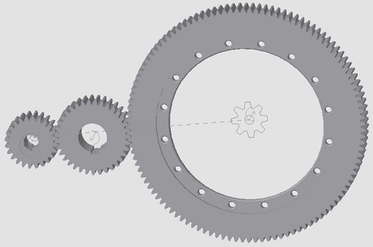
The spur gear system comprises three components: a pinion (z₁=24), an idler gear (z₂=36), and a large gear (z₃=72). The assembly steps in Creo 5.0 are:
- Define Reference Axes:
- Create a primary axis (Axis 1) at the intersection of the FRONT and RIGHT planes.
- Offset two parallel axes (Axis 2 and Axis 3) with center distances of 230 mm and 900 mm.
- Assemble Components:
- Use the Assemble tool to position the pinion, idler gear, and large gear on their respective axes.
- Align gear planes to ensure proper meshing.
| Gear | Center Distance | Axis Alignment |
|---|---|---|
| Pinion | 230 mm | Parallel to Axis 1 |
| Idler Gear | 230 mm → 900 mm | Between Axis 2 and 3 |
| Large Gear | 900 mm | Parallel to Axis 1 |
2.2 Defining Gear Pairs and Motion
To simulate spur gear interactions, Gear Pair connections are established in the Mechanism module:
- Pinion-Idler Pair:
- Select the pinion’s axis as the driving gear.
- Set the pitch diameter to 168 mm (d₁ = m·z₁).
- Idler-Large Gear Pair:
- Define the idler gear’s axis as the intermediate driver.
- Specify pitch diameters for both gears to maintain speed ratios.
A Servo Motor is applied to the pinion’s axis to drive the system. The motion profile includes angular acceleration and velocity parameters.
Motion Simulation and Results
3.1 Kinematic Analysis
The simulation evaluates rotational speeds and transmission accuracy:
- Input Parameters:
- Servo Motor: Angular velocity = 100 rpm (pinion).
- Simulation Time: 10 seconds.
- Output Metrics:
- Speed ratio between gears.
- Linear velocity at gear contact points.
| Gear | Theoretical Speed (rpm) | Simulated Speed (rpm) | Error |
|---|---|---|---|
| Pinion | 100 | 100 | 0% |
| Idler | 66.67 | 66.5 | 0.25% |
| Large Gear | 33.33 | 33.2 | 0.39% |
The results confirm the spur gear system’s adherence to theoretical speed ratios, validating the design’s kinematic accuracy.
3.2 Dynamic Behavior
Using Creo 5.0’s Measure tool, dynamic parameters such as angular velocity and acceleration are plotted. Key observations include:
- Velocity Stability: The pinion maintains a near-constant speed, with minor fluctuations due to meshing impacts.
- Acceleration Peaks: Transient spikes occur during gear engagement, highlighting areas for stress analysis.
Conclusion
This study demonstrates the efficacy of Creo 5.0 in parameterized design and motion simulation of spur gear systems. By automating critical steps—from involute curve generation to gear pairing—the software reduces design iterations and ensures geometric precision. Motion simulations further validate the system’s kinematic performance, enabling engineers to optimize spur gear assemblies for real-world applications. Future work will extend this methodology to helical and bevel gears, enhancing the versatility of the design framework.