According to the performance requirements of the reducer, the technical parameters are determined on the basis of the above structural scheme, and eight links are discussed, including transmission ratio distribution, motion and motion parameter design, mechanical model establishment, strength design of involute gear pair, shafting structure and strength check, bearing life check, box structure and strength stiffness design, lubrication and seal design of the reducer.
1. Transmission ratio distribution
According to the load tension F and the load linear speed V, the effective power PW of the motor is calculated through the formula, the bearing type is selected by referring to the efficiency table, and the total efficiency is calculated through the efficiency of the involute gear and the coupling η In general, the required power PD of the motor can be calculated according to the formula. Select the motor by looking up the table. The rated power of the selected motor should be equal to or slightly greater than the value of PD.
According to the diameter D of the drum and the linear speed V of the load, the rotation speed NW of the working machine is calculated by formula (1):

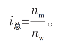
Then, according to the determined motor table, the full load speed nm of the motor is obtained, and the total transmission ratio I is calculated by formula (2):

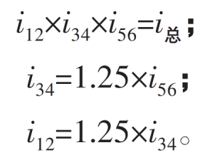
Determine a = 1.25 according to the transmission ratio formula, and calculate the primary transmission ratio i12, secondary transmission ratio i34 and tertiary transmission ratio i56 through formula (3) – (5):

2. Motion and motion parameter design
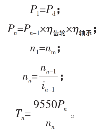
According to the required power PD and full load speed nm of the motor, and η Involute gear η The power PN, rotational speed NN and torque TN of each shaft can be calculated by formula (6) to formula (10) according to the bearing and transmission ratio of each stage:

3. Establishment of mechanical model
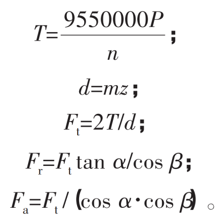
According to the known parameters, transfer power P, rotational speed n, modulus m, number of teeth Z, pressure angle α、 Helix angle β, Calculate the involute gear circumferential force ft, the involute gear radial force FR and the involute gear axial force FA through equations (11) to (15):

Where: t is torque; D is the pitch circle diameter of the involute gear.
Then, according to the obtained circumferential force, radial force and axial force of the involute gear, the mechanical model of the shaft system is calculated.
