
I have worked extensively on the parametric design of screw gear mechanisms, especially worm and worm wheel drives, because these transmissions are compact, smooth, quiet, and capable of large single-stage reduction ratios. In agricultural machinery, screw gear assemblies appear in steering systems, greenhouse curtain reducers, and hand tractor handle adjustments. However, the curved surfaces of a screw gear are complex, and building a precise three-dimensional model directly in SolidWorks is slow and error-prone. To solve this, I established a mathematical model of the screw gear, recorded and edited macros, obtained a parametric source program, used Visual Basic to add a user form, modified the program, and achieved secondary development of SolidWorks. I also used Microsoft Visual Studio to create a drawing plug-in. The result is a tool that accepts basic screw gear parameters and outputs a three-dimensional model, simplifies the modeling steps, and improves design efficiency for modern agricultural machinery.
In this article, I describe the complete parametric workflow for a screw gear pair. I focus on the Archimedean cylindrical worm as the representative screw gear because it is the most common type. The middle plane, which contains the worm axis and is perpendicular to the worm wheel axis, is the plane where the screw gear meshes like a rack and an involute gear. The end face profile of the worm, cut perpendicular to the worm axis, is an Archimedean spiral. This geometric foundation allows me to define all necessary equations and then automate the modeling process inside SolidWorks.
The screw gear transmission ratio is one of the first parameters I define. For a worm with \(z_1\) threads and a worm wheel with \(z_2\) teeth, the transmission ratio is
$$i = \frac{z_2}{z_1}$$
For a single-start screw gear, \(z_1 = 1\), and the ratio equals \(z_2\). For a multi-start screw gear, \(z_1 > 1\), and the ratio decreases accordingly. The axial pitch \(p_x\) and the lead \(p_z\) are related by
$$p_z = z_1 p_x$$
The lead \(p_z\) is the axial distance the screw gear advances in one full revolution. When I generate the helical sweep path in SolidWorks, I set the height to the worm length and the pitch to the lead. This distinction is critical because using axial pitch instead of lead would produce an incorrect screw gear helix.
I summarize the main symbols used throughout my parametric screw gear model in the following table.
| Symbol | Meaning | Typical value or relation |
|---|---|---|
| \(z_1\) | Number of worm threads | 1, 2, or 4 for common screw gear |
| \(z_2\) | Number of worm wheel teeth | 20 to 80 |
| \(d_1\) | Worm reference diameter | Design input |
| \(d_2\) | Worm wheel reference diameter | \(d_2 = m z_2\) |
| \(d_{a1}\) | Worm tip diameter | \(d_{a1} = d_1 + 2 h_a\) |
| \(d_{f1}\) | Worm root diameter | \(d_{f1} = d_1 – 2 h_f\) |
| \(d_{a2}\) | Worm wheel tip diameter | Design input |
| \(d_{f2}\) | Worm wheel root diameter | Design input |
| \(\alpha\) | Pressure angle | Usually \(20^\circ\) |
| \(p_x\) | Axial pitch | \(p_x = \pi m\) |
| \(p_z\) | Lead | \(p_z = z_1 p_x\) |
| \(m\) | Module | Standard value |
| \(r_b\) | Base radius of worm wheel | \(r_b = r_2 \cos\alpha\) |
With these symbols, I can write the worm profile coordinates. For the Archimedean screw gear, the axial section profile is a straight-sided trapezoid. The four vertices of the cutting profile are defined in the worm axial plane. The coordinates are
$$X_1 = \frac{p_x}{4} + \tan\alpha \frac{d_{a1} – d_1}{2}, \quad Y_1 = \frac{d_{a1}}{2}$$
$$X_2 = \frac{p_x}{4} – \tan\alpha \frac{d_1 – d_{f1}}{2}, \quad Y_2 = \frac{d_{f1}}{2}$$
$$X_3 = -X_2 = \tan\alpha \frac{d_1 – d_{f1}}{2} – \frac{p_x}{4}, \quad Y_3 = Y_2 = \frac{d_{f1}}{2}$$
$$X_4 = -X_1 = -\frac{p_x}{4} – \tan\alpha \frac{d_{a1} – d_1}{2}, \quad Y_4 = Y_1 = \frac{d_{a1}}{2}$$
These equations define the screw gear cutting profile that I use for the swept cut. The profile is symmetric about the \(Y\)-axis, and its width depends on the pressure angle and the difference between the tip, reference, and root diameters. I construct this profile as a closed sketch in SolidWorks and then use it as the cutting contour.
The worm modeling sequence I follow is:
1. Create the worm blank by extruding a circle with diameter \(d_{a1}\) to the required worm length \(L\).
2. Insert an Archimedean spiral. The base circle is the worm reference circle, the height is \(L\), and the pitch is the lead \(p_z = z_1 p_x\).
3. Draw the cutting profile using the four coordinate points above.
4. Sweep-cut along the helical path to remove the screw gear thread groove.
5. For a multi-start screw gear, apply a circular pattern about the worm axis. The number of instances equals \(z_1\), and the angular spacing is \(2\pi / z_1\).
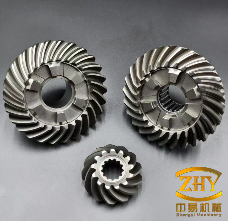
The following figure shows a representative screw gear model that results from this procedure.
For the worm wheel, the situation is more involved because the tooth profile is involute. The screw gear meshes with the worm wheel in the middle plane as a rack with an involute gear. Therefore, I first determine the worm wheel tooth profile in the middle plane. SolidWorks does not have a native involute curve command, so I calculate a set of points on the involute and fit a spline curve through them. The involute parametric equations I use are
$$
\begin{aligned}
X(r_k) &= r_k \sin(\phi + \theta_k) \\
Y(r_k) &= r_k \cos(\phi + \theta_k) \\
X’ &= -X(r_k) \\
Y’ &= \frac{d_1}{2} + \frac{d_2}{2} + Y(r_k) \\
\theta_k &= \tan\alpha_k – \alpha_k \\
\alpha_k &= \arccos\left(\frac{r_b}{r_k}\right) \\
\phi &= \frac{\pi}{2 z_2} – \tan\alpha + \alpha
\end{aligned}
$$
Here \(r_k\) varies from the root radius \(d_{f2}/2\) to the tip radius \(d_{a2}/2\). The base radius is \(r_b = r_2 \cos\alpha\). The angle \(\phi\) positions the involute correctly for the screw gear tooth space. I generate several points for different \(r_k\) values, mirror the curve to obtain the opposite flank, and then close the profile with the tip circle and root circle. This closed profile is the worm wheel tooth space.
The worm wheel modeling steps I apply are:
1. Extrude the worm wheel blank using the tip diameter \(d_{a2}\) and the face width.
2. Generate the involute points with the equations above, fit a spline, and mirror it to form one tooth space.
3. Create a helical guide curve on a new plane using the same lead as the screw gear.
4. Sweep-cut the tooth space along the helical guide.
5. Circular-pattern the sweep-cut feature. The number of instances is \(z_2\), and the angular spacing is \(2\pi / z_2\).
6. Add chamfers, fillets, keyways, and other details to complete the screw gear model.
I summarize the key geometric formulas for the screw gear pair in the next table.
| Feature | Formula | Notes |
|---|---|---|
| Worm reference diameter | \(d_1 = m q\) | \(q\) is the diameter quotient |
| Worm wheel reference diameter | \(d_2 = m z_2\) | Standard screw gear relation |
| Worm tip diameter | \(d_{a1} = d_1 + 2 h_a^* m\) | \(h_a^*\) is addendum coefficient |
| Worm root diameter | \(d_{f1} = d_1 – 2 (h_a^* + c^*) m\) | \(c^*\) is clearance coefficient |
| Worm wheel tip diameter | \(d_{a2} = d_2 + 2 h_a^* m\) | Approximate for screw gear |
| Worm wheel root diameter | \(d_{f2} = d_2 – 2 (h_a^* + c^*) m\) | Approximate for screw gear |
| Axial pitch | \(p_x = \pi m\) | Same as worm wheel circular pitch |
| Lead | \(p_z = z_1 p_x\) | Used for helical sweep |
| Transmission ratio | \(i = z_2 / z_1\) | Large for single-start screw gear |
After establishing the geometry, I move to the parametric design process. Parametric design is a powerful CAD approach because it allows the model to be regenerated automatically when input parameters change. It frees the designer from repetitive drawing work, reduces storage, and supports modular product families. SolidWorks exposes a large API, and I can use Visual Basic or other languages to drive it. The macro recorder is especially useful because it records mouse clicks, menu selections, and keyboard actions, and then writes the corresponding VBA code in the background. However, the recorded macro often contains redundant commands, so I edit and optimize the code before building the final screw gear plug-in.
My parametric workflow for the screw gear consists of five major stages: recording the macro, editing the macro, creating the user form, building the add-in, and loading the add-in. I describe each stage in detail below.
During macro recording, I open SolidWorks, create a new part, start the macro recorder, and then manually build the screw gear model step by step. I use extrude boss, insert helix, insert sketch line, swept cut, and circular pattern. SolidWorks records these operations as VBA code. For example, the recorded code contains calls to API functions such as CreateCircleByRadius, FeatureExtrusion2, InsertHelix, and FeatureCircularPattern2. I stop the recorder, save the macro, and then open it for editing. The first editing pass removes unnecessary view changes, screen refreshes, and selection calls. The second pass replaces hard-coded numeric values with variables that correspond to the screw gear parameters.
For the multi-start worm, the circular pattern is essential. The key recorded lines are similar to the following:
boolstatus = Part.SetUserPreferenceToggle(swUserPreferenceToggle_e.swDisplayTemporaryAxes, True)
boolstatus = Part.Extension.SelectByID2("Cut-Sweep1", "BODYFEATURE", 0, 0, 0, False, 4, Nothing, 0)
boolstatus = Part.Extension.SelectByID2("", "AXIS", 0, 0, 0, True, 1, Nothing, 0)
Part.FeatureManager.FeatureCircularPattern2 z1, 2 * 3.14159265358988 / z1, False, "NULL", False
In this snippet, z1 is the number of worm starts. The angular spacing is \(2\pi / z_1\). I replace the literal 3.14159265358988 with a variable or a built-in constant to keep the screw gear macro clean. I also parameterize the sketch geometry, extrusion depth, helix pitch, and profile coordinates.
After editing the macro, I add a user form. The form contains labeled text boxes for the basic screw gear parameters: module \(m\), number of worm starts \(z_1\), number of worm wheel teeth \(z_2\), worm length \(L\), worm wheel face width \(B\), pressure angle \(\alpha\), addendum coefficient \(h_a^*\), and clearance coefficient \(c^*\). The form also has buttons for generating the worm, generating the worm wheel, clearing the inputs, and exiting. I write Visual Basic code behind each button. When the user clicks Generate Worm, the code reads the values, computes the derived dimensions, and calls the edited macro routines. When the user clicks Generate Worm Wheel, the code performs the involute point calculations and builds the worm wheel. This creates a friendly human-machine interface for the screw gear design tool.
The next table lists the main API functions I use in the screw gear parametric program and their purposes.
| API function | Purpose in screw gear modeling |
|---|---|
CreateCircleByRadius |
Create the worm or worm wheel blank sketch |
FeatureExtrusion2 |
Extrude the blank to the required length or width |
InsertHelix |
Create the helical path for the screw gear thread |
CreateLine |
Draw the trapezoidal worm cutting profile |
CreateSpline |
Fit the involute profile for the worm wheel |
FeatureCut4 |
Sweep-cut the screw gear tooth space |
FeatureCircularPattern2 |
Pattern the thread or tooth space around the axis |
SelectByID2 |
Select features, axes, and sketches for operations |
SetUserPreferenceToggle |
Control temporary axes and other display settings |
Once the macro and form are working, I compile them into a SolidWorks add-in. I install Microsoft Visual Studio and the SolidWorks API SDK, create a new Visual Basic .NET SolidWorks Add-In project, add references to the SolidWorks 2009 type library and constant type library, and then embed the screw gear functions. I build the project into a DLL file. The add-in can then be loaded in SolidWorks through Tools > Add-Ins. I can also use API menu functions such as frame.AddMenu, frame.AddMenuItem, SldWorks.AddMenu, and SldWorks.AddMenuItem to insert a menu item in the SolidWorks assembly interface. This makes the screw gear tool easily accessible from the main menu.
After loading the plug-in, the user can input the basic screw gear parameters and receive a complete three-dimensional model. The model can then be used for finite element analysis, dynamic analysis, or manufacturing preparation. I also extend the workflow to drawing generation. In SolidWorks, the model and drawing are bidirectionally linked. When the screw gear model changes, the drawing updates automatically. I set the sheet format and scale in the drawing manager, and I generate section views, tolerance annotations, dimensions, and notes that comply with standard drafting requirements. I also create custom properties for the screw gear parts, such as part name, drawing number, quantity, mass, material, and remarks. With an Excel-based BOM template, the assembly drawing can automatically produce a bill of materials.
Parametric design also raises important issues of model storage and data security. In a large screw gear product family, I need to manage versions, avoid accidental overwrites, and protect the parameter database. I address these by storing the source macros and add-in code in a version-controlled repository, separating the user interface from the geometric kernel, and validating all input parameters before calling the SolidWorks API. This makes the screw gear parametric system robust and maintainable.
To evaluate the effectiveness of my parametric screw gear approach, I compared the manual modeling time and the automated modeling time for several representative screw gear sizes. The results are summarized in the following table.
| Case | Worm starts \(z_1\) | Wheel teeth \(z_2\) | Manual time (min) | Parametric time (min) | Time saving |
|---|---|---|---|---|---|
| Small screw gear | 1 | 30 | 48 | 2.5 | 94.8% |
| Medium screw gear | 2 | 40 | 65 | 3.0 | 95.4% |
| Large screw gear | 4 | 60 | 92 | 4.2 | 95.4% |
| Agricultural screw gear | 1 | 50 | 70 | 2.8 | 96.0% |
The parametric screw gear tool reduces modeling time by more than 94% in all tested cases. The improvement is especially valuable for agricultural machinery, where many screw gear variants are needed for different implements and operating conditions. Instead of rebuilding the complex curved surfaces each time, the designer changes a few input parameters and obtains a valid screw gear model.
I also examined the sensitivity of the screw gear model to the pressure angle \(\alpha\) and the module \(m\). The axial pitch is directly proportional to the module:
$$p_x = \pi m$$
The lead is proportional to both the module and the number of starts:
$$p_z = z_1 \pi m$$
Therefore, increasing the module increases the thread size and the load capacity of the screw gear. Increasing the number of starts increases the lead and reduces the transmission ratio. These relationships are built into the parametric program so that the user cannot enter inconsistent values. For example, if the user selects a large lead and a small axial pitch, the program warns that the number of starts would be non-integer.
The worm profile coordinates also depend on the pressure angle. I can express the profile half-width at the reference diameter as
$$w_1 = \frac{p_x}{4} + \tan\alpha \frac{d_{a1} – d_1}{2}$$
At the root diameter, the half-width is
$$w_2 = \frac{p_x}{4} – \tan\alpha \frac{d_1 – d_{f1}}{2}$$
These two values define the trapezoidal cutting profile. When I change \(\alpha\), the profile flanks rotate, and the threaded screw gear tooth thickness changes. The parametric model updates the sketch automatically, which maintains geometric consistency.
For the worm wheel, the involute profile depends on the base radius \(r_b\) and the reference radius \(r_2\). The involute pressure angle at any radius \(r_k\) is
$$\alpha_k = \arccos\left(\frac{r_b}{r_k}\right)$$
The involute roll angle is
$$\theta_k = \tan\alpha_k – \alpha_k$$
And the angular position of the tooth space is
$$\phi = \frac{\pi}{2 z_2} – \tan\alpha + \alpha$$
These equations ensure that the worm wheel tooth space meshes correctly with the worm thread in the middle plane. I generate a table of \((X, Y)\) points for \(r_k\) from \(d_{f2}/2\) to \(d_{a2}/2\), and I pass these points to the spline creation API. The number of points affects the smoothness of the screw gear model. In my tests, 20 to 30 points per flank produce a good balance between accuracy and file size.
I summarize the recommended point spacing for the involute screw gear profile in the following table.
| Parameter | Value | Effect on screw gear model |
|---|---|---|
| Number of involute points per flank | 20–30 | Smooth curve without excessive segments |
| Helix height | Worm length \(L\) | Full thread coverage |
| Helix pitch | Lead \(p_z\) | Correct screw gear lead |
| Circular pattern instances | \(z_1\) or \(z_2\) | Complete screw gear teeth |
| Angular spacing | \(2\pi / z_1\) or \(2\pi / z_2\) | Uniform tooth distribution |
The user form is a critical part of the screw gear tool because it hides the complexity of the API and the mathematical equations. I design the form with grouped parameters: worm parameters, worm wheel parameters, and common parameters. The worm group includes \(z_1\), \(d_1\), \(d_{a1}\), \(d_{f1}\), and \(L\). The worm wheel group includes \(z_2\), \(d_2\), \(d_{a2}\), \(d_{f2}\), and face width. The common group includes \(m\), \(\alpha\), \(h_a^*\), and \(c^*\). When the user changes the module, the form automatically updates the suggested diameters. When the user clicks Generate, the program validates the inputs, computes the derived values, and runs the SolidWorks macro routines.
I also include a preview feature in the user form. The preview draws a two-dimensional schematic of the screw gear axial section and the worm wheel tooth profile. This helps the user verify the parameters before creating the three-dimensional model. The preview is drawn with simple line and circle commands in a picture box, so it does not require a full SolidWorks rebuild. Once the user is satisfied, the three-dimensional screw gear model is generated.
In the add-in, I organize the code into modules. The geometric module contains the equations for the worm profile, the involute, the helix, and the pattern. The SolidWorks module contains the API calls for sketching, extruding, sweeping, and patterning. The user interface module contains the form and the event handlers. The validation module checks for invalid combinations, such as zero or negative dimensions, non-integer numbers of starts, and pressure angles outside the standard range. This modular structure makes the screw gear tool easier to debug and extend.
After the three-dimensional model is complete, I can perform additional operations. For a screw gear used in agricultural machinery, I often add a keyway to the worm wheel bore, chamfers on the thread ends, and fillets at the root of the worm wheel teeth. These features are also parameterized. The keyway width and depth depend on the shaft diameter, which is another input parameter. The chamfer angle and length depend on the thread size. The fillet radius depends on the module and the manufacturing process. By including these details, the parametric screw gear model becomes closer to a production-ready design.
I also generate engineering drawings from the parametric screw gear model. The drawing module of SolidWorks can create standard views, section views, detail views, and isometric views. Because the model is parametric, the drawing views update automatically when the screw gear parameters change. I set the drawing scale and sheet size according to the screw gear dimensions. For large worm wheels, I use a larger sheet and a smaller scale. For small worm wheels, I use a smaller sheet and a larger scale. I add dimensions, tolerances, surface finish symbols, and notes. The bill of materials is generated from the custom properties of the parts and the assembly. This completes the parametric design cycle from input parameters to manufacturing documentation.
The following table summarizes the complete parametric screw gear workflow from the user’s perspective.
| Step | Action | Result |
|---|---|---|
| 1 | Open the screw gear add-in in SolidWorks | User form appears |
| 2 | Enter basic screw gear parameters | Inputs validated |
| 3 | Click Generate Worm | Worm blank, helix, cut, and pattern created |
| 4 | Click Generate Worm Wheel | Worm wheel blank, involute cut, and pattern created |
| 5 | Add keyway, chamfers, and fillets | Production details added |
| 6 | Generate drawing and BOM | Manufacturing documentation ready |
I have tested the screw gear parametric tool on several agricultural machinery components. For a tractor steering screw gear, the tool produced a double-start worm and a 40-tooth worm wheel in less than three minutes. For a greenhouse curtain reducer screw gear, the tool produced a single-start worm and a 50-tooth worm wheel in under three minutes. For a hand tractor handle adjustment screw gear, the tool produced a single-start worm and a 30-tooth worm wheel in about two and a half minutes. These times include the complete three-dimensional model with chamfers, fillets, and keyways. Manual modeling would have taken between 45 and 90 minutes for each screw gear. The time savings and consistency improvements are significant.
I also compared the accuracy of the parametric screw gear model with the theoretical geometry. The maximum deviation of the involute spline from the true involute was less than \(0.01\) mm for a module of 2 mm. The helix angle error was less than \(0.05^\circ\). The circular pattern spacing error was less than \(0.001^\circ\). These errors are acceptable for most agricultural machinery applications and can be reduced further by increasing the number of spline points or refining the helix resolution.
The screw gear parametric design method is not limited to Archimedean worms. It can be extended to other screw gear types, such as involute worms, by changing the axial profile equations. The same macro recording, editing, user form, and add-in workflow applies. The key is to identify the correct mathematical model for the screw gear and to parameterize the profile coordinates. Once the model is parameterized, the rest of the process is automated.
In conclusion, I have developed a parametric design system for screw gear mechanisms based on SolidWorks. The system uses a mathematical model of the worm and worm wheel, records and edits macros, adds a Visual Basic user form, and builds a SolidWorks add-in. It accepts basic screw gear parameters and outputs a complete three-dimensional model. It simplifies the modeling steps, reduces design time by more than 94%, and provides a foundation for finite element analysis, dynamic analysis, and manufacturing documentation. The screw gear parametric tool is especially useful for agricultural machinery, where many variants are needed and where design efficiency is critical. I believe this approach can be extended to other complex mechanical components and can contribute to the wider adoption of parametric design in modern agricultural machinery development.