
In the field of mechanical transmission, spiral bevel gears play a critical role in transferring motion and power between intersecting axes, particularly in automotive, aerospace, and industrial machinery. The ‘non-zero’ transmission spiral bevel gear, an innovation promoted under China’s national key scientific and technological achievements, has demonstrated superior performance in terms of load capacity, noise reduction, and efficiency. However, the traditional manual drafting of spiral bevel gear part drawings is time-consuming, error-prone, and hampers the widespread adoption of this technology. As an engineer involved in this domain, I have developed a parametric design system for spiral bevel gear CAD graphics to automate and optimize the drawing process. This article delves into the methodologies and techniques of parametric design for spiral bevel gears, focusing on system architecture, database integration, and practical implementation. By leveraging AutoCAD2000 as a platform and ObjectARX2000 for customization, this system enables designers to generate precise and usable spiral bevel gear part drawings within minutes, significantly shortening design cycles and enhancing quality. Through extensive testing, the system has proven to be user-friendly, reliable, and easily maintainable, facilitating the broader application of spiral bevel gear technology.
The core of this parametric design system revolves around the spiral bevel gear, a complex component requiring meticulous attention to geometric parameters and manufacturing tolerances. Traditional design approaches often involve repetitive calculations and manual drafting, leading to inconsistencies and delays. To address this, I have constructed a comprehensive CAD graphics system that integrates parametric modeling with a robust database. The system allows for the automatic generation of part drawings based on input parameters, reducing human error and accelerating production. In this discussion, I will explore the system’s overall structure, the creation of databases, key elements of parametric design, and a practical example to illustrate its efficacy. Throughout, the term ‘spiral bevel gear’ will be emphasized to underscore its centrality in this work.
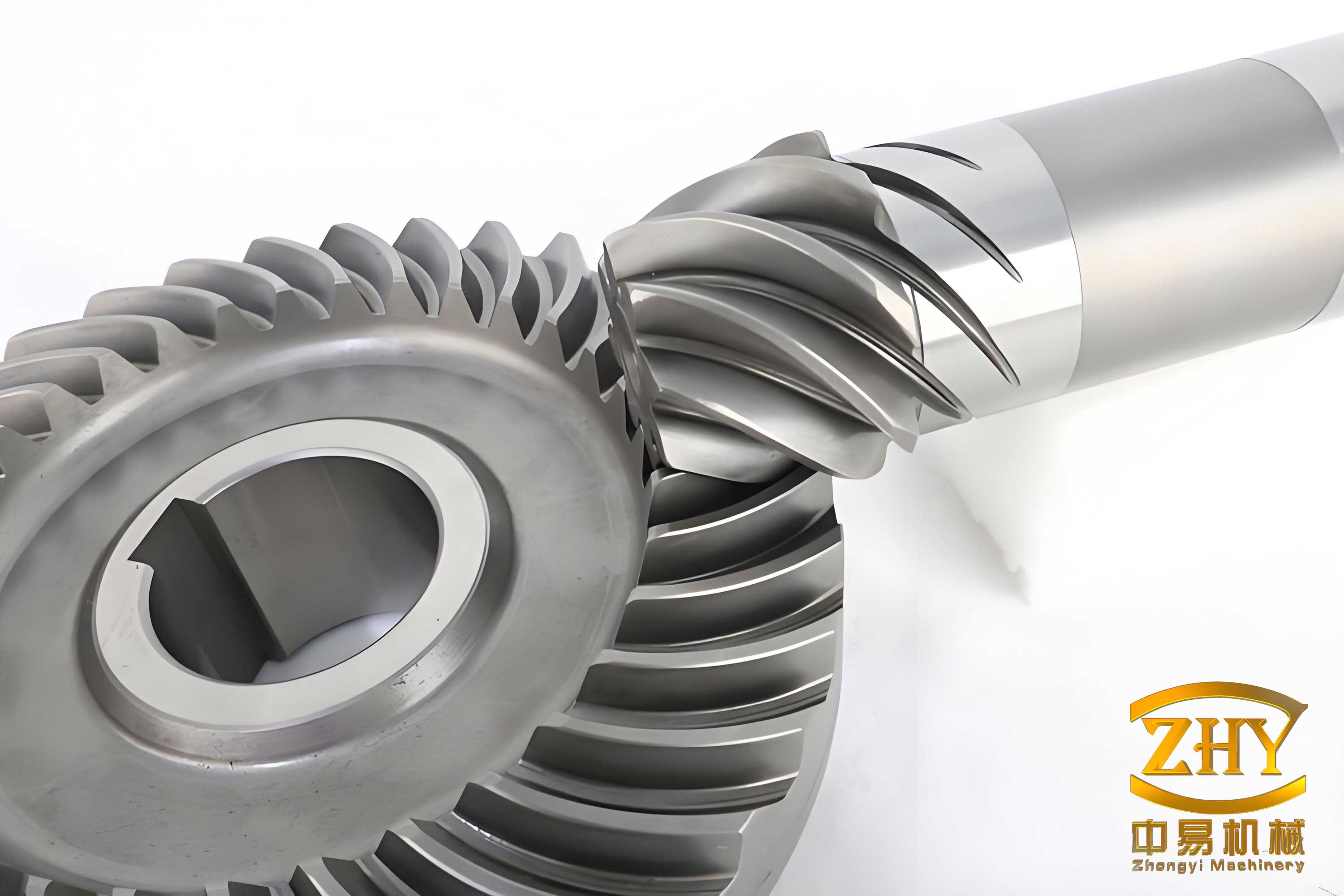
The parametric design system for spiral bevel gears is built on a modular architecture that ensures flexibility and scalability. At its foundation, the system employs AutoCAD2000 as the graphical environment, utilizing ObjectARX2000 for application development in Microsoft Visual C++ 6.0. This combination provides a powerful toolkit for creating custom commands and automating drawing tasks. The overall structure, as I have designed it, comprises several interconnected modules: a database management system, a shape classification library, a primitive element library, an initialization module, and a drawing generation engine. Each module contributes to the seamless parametric design of spiral bevel gear part drawings, enabling rapid adaptation to varying gear specifications. The integration of these components ensures that designers can focus on high-level decisions rather than tedious manual work.
To support the parametric design process, I established a comprehensive database that categorizes all necessary data for spiral bevel gear design and manufacturing. This database is essential for storing standard values, tolerances, material properties, and tooling information, which are frequently referenced during drawing generation. The data is organized into several classes, as summarized in Table 1. Each class contains relevant standards and charts, allowing the system to retrieve information dynamically based on design requirements. For instance, when specifying dimensions or tolerances for a spiral bevel gear, the system queries the database to ensure compliance with national standards. This structured approach not only streamlines the design process but also enhances accuracy and consistency across different spiral bevel gear projects.
| Class | Description | Examples |
|---|---|---|
| Basic Standards | Fundamental geometric and mechanical standards | Module series, pressure angles |
| Tolerances and Fits | Dimensional and geometric tolerances | ISO tolerance grades, fit types |
| Connections and Fasteners | Standard fastening elements | Bolts, keys, splines |
| Tools and Materials | Cutting tools and material properties | Tool radii, steel grades |
| Gear Processes | Manufacturing and inspection data | Heat treatment specs, inspection methods |
Parametric design for spiral bevel gears involves several key steps, each contributing to the automatic generation of part drawings. First, I classified spiral bevel gear shapes based on structural features such as external轮廓, internal孔形状, and加工 elements. This classification enables the system to select appropriate template shapes from a graphical database. For example, common盘形 spiral bevel gears have a standardized form that can be parameterized using variables for dimensions like hub diameter and web thickness. By tagging these dimensions with alphabetic codes, as shown in generic shape diagrams, the system allows users to input specific values during design. This approach ensures that diverse spiral bevel gear configurations can be accommodated without redrawing from scratch.
Next, I developed a primitive library containing frequently used drawing elements such as dimension lines, surface roughness symbols, geometric tolerances, title blocks, and technical note tables. These primitives are stored as parameterized blocks in a素 database, enabling their insertion into part drawings with customizable attributes. For instance, when标注粗糙度 for a spiral bevel gear tooth surface, the system retrieves the appropriate symbol from the library and places it at user-specified locations. Similarly, title blocks and特性 tables are populated dynamically based on input data, reducing manual entry errors. This library-based method enhances efficiency, as designers can reuse standardized components across multiple spiral bevel gear drawings.
Initializing the drawing environment is a crucial step in ensuring consistency and adherence to drafting standards. I implemented a macro-driven initialization routine that sets parameters like drawing scale, line types, layers, dimension styles, and sheet sizes. For example, layers are defined for different line types—centerlines on one layer,轮廓 lines on another—with specific colors and linetypes assigned. This is achieved through commands encapsulated in macros, such as:
#define LAYER_SET2 acedCommand(RTSTR, “LAYER”, RTSTR, “M”, RTSTR, “2”, RTSTR, “C”, RTSHORT, 3, RTSTR, ” “, RTSTR, “L”, RTSTR, “center”, RTSTR, “”, RTSTR, “”, 0)
#define LAYER_IN1 acedCommand(RTSTR, “LAYER”, RTSTR, “S”, RTSTR, “1”, RTSTR, “”, 0)
These macros streamline the setup process, allowing the system to configure the AutoCAD environment automatically before drawing commences. By standardizing the environment, I ensure that all spiral bevel gear part drawings maintain a uniform appearance and comply with industrial norms.
The coordinate system is another fundamental aspect of parametric design. I adopted the World Coordinate System (WCS) in AutoCAD2000 as the default reference for all geometric calculations. This choice simplifies point坐标 determination and ensures that all elements are positioned relative to a consistent origin. For spiral bevel gear drawings, I typically set a base point (BASEPT) at the intersection of the gear axis and the pitch cone, from which other points are computed. This approach facilitates symmetric drawing, as spiral bevel gears are often镜像 about their central axis. By calculating型值点 coordinates relative to BASEPT, the system can generate precise几何 shapes without manual intervention.
To illustrate the coordinate computation, consider the齿形 portion of a spiral bevel gear, which requires seven key parameters:齿宽 (b),节锥距 (R_w),齿顶高 (h_a),齿根高 (h_f),节锥角 (δ),面锥角 (δ_a), and根锥角 (δ_f). These parameters are derived from prior design calculations and passed via data files. The coordinates for points on the tooth profile can be expressed using geometric formulas. For instance, the coordinates of a point on the pitch cone surface in a local coordinate system can be given by:
$$ x = R_w \cdot \sin(\delta) \cdot \cos(\theta) $$
$$ y = R_w \cdot \sin(\delta) \cdot \sin(\theta) $$
$$ z = R_w \cdot \cos(\delta) $$
where θ is the angular position around the axis. By parameterizing these equations, the system generates the tooth profile accurately for any spiral bevel gear configuration. This mathematical foundation ensures that the drawn spiral bevel gear reflects the intended design specifications.
Inputting design requirements is facilitated through a user-friendly dialog interface, where designers can select gear shapes, input轮体 parameters, and specify additional features like keys or bolt holes. For轴 spiral bevel gears, a dedicated dialog allows the selection of shaft segments with customizable dimensions, as illustrated in a dialog box example. Users can also input values for未注倒角 and未注圆角, which are applied automatically during drawing generation. This interactive process ensures that all necessary parameters for the spiral bevel gear are captured before proceeding to drawing computation.
Once inputs are received, the system calculates the coordinates of all型值点 and connects them to form the basic part drawing. This includes generating the gear body, adding keys or bolts in剖视图, and applying chamfers or fillets as specified. The drawing process is executed in the background, with algorithms ensuring that all elements are placed correctly. For example, after drawing the轮廓,剖面线 are added to enclosed areas to represent sections, adhering to standard drafting practices for spiral bevel gears. This automated approach minimizes manual drawing efforts and reduces the potential for errors.
Dimensioning and annotation are critical for manufacturing clarity. The system automatically标注尺寸 lines and angles based on the computed geometry, with precision up to minutes and seconds for angular dimensions.粗糙度,尺寸公差, and形位公差 are标注 cyclically through a loop that allows designers to select positions and input values. The system queries the database to retrieve standard tolerance values based on basic sizes and accuracy grades, then places the annotations accordingly. This iterative process continues until the designer confirms completion, ensuring that all necessary tolerances for the spiral bevel gear are included.
The final steps involve adding the图框,标题栏,特性表, and技术要求. The system determines the sheet size and scale based on the drawing’s extents and the selected standard (e.g., ISO A3 or A4). Title blocks and property tables are filled with data from user inputs and design files, while technical requirements are assembled from predefined clauses or custom entries. These elements are positioned appropriately to create a polished spiral bevel gear part drawing. Importantly, all components—such as轴段 selection, bolt drawing, and tolerance标注—can be modified independently, allowing designers to refine the drawing until满意.
To demonstrate the system’s capabilities, I present a design example for a pair of spiral bevel gears. The basic parameters are listed in Table 2, which includes齿数,螺旋角,压力角, and other关键 dimensions. These parameters are typical for spiral bevel gears used in heavy machinery, showcasing the system’s versatility.
| Parameter | Pinion (Small Gear) | Gear (Large Gear) |
|---|---|---|
| Number of teeth, z | 33 | 33 |
| Midpoint spiral angle, β (°) | 35 | 35 |
| Nominal pressure angle, α (°) | 20 | 20 |
| Outer pitch cone distance, R_w (mm) | 104.809 | 104.809 |
| Addendum coefficient, h_a* | 1.047 | 1.047 |
| Radial modification coefficient, x | -0.2 | -0.2 |
| Tangential modification coefficient, x_t | 0 | 0 |
| Face width, b (mm) | 31.5 | 31.5 |
| Cutter radius, r (mm) | 114.3 | 114.3 |
| Shaft angle, Σ (°) | 90 | 90 |
Using the ‘non-zero’ transmission method, the total contact ratio for this spiral bevel gear pair is optimized. The contact ratio (ε) is a critical metric for gear performance, calculated as:
$$ ε = \frac{\text{Length of action}}{\text{Base pitch}} $$
For spiral bevel gears, this can be derived from geometric parameters, resulting in an increase from 1.57648 in traditional designs to 2.10236 in this case. This enhancement improves load distribution and reduces noise, key advantages of spiral bevel gears. Additionally, the unit module tooth tip thickness for the pinion is optimized from 0.276 to 0.365, avoiding issues like undercutting or interference. After parameterization, the system generates part drawings for both gears, as depicted in representative figures (though not referenced by number). These drawings include all necessary dimensions, tolerances, and notes, ready for manufacturing.
The parametric design system for spiral bevel gears offers numerous benefits. By automating the drawing process, it reduces design time from days to minutes, while ensuring accuracy and compliance with standards. The integration of databases and primitive libraries allows for easy maintenance and expansion, accommodating new spiral bevel gear variants or updated standards. From my experience, the system is stable and user-friendly, requiring minimal training for designers. Its modular architecture supports customization, enabling adaptation to specific industry needs for spiral bevel gear production.
In conclusion, this article has detailed the parametric design methodology for a spiral bevel gear CAD graphics system, emphasizing its structure, implementation, and practical application. The system leverages advanced software tools to transform the design of spiral bevel gears from a manual, error-prone task into an efficient, automated process. By repeatedly focusing on spiral bevel gears throughout the discussion, I underscore their importance in mechanical transmission and the value of parametric design in advancing their technology. Future work may involve integrating simulation modules for stress analysis or extending the system to other gear types, but the core principles established here provide a solid foundation for innovation in spiral bevel gear design.