
As an engineer deeply involved in computer-aided design and manufacturing, I have extensively explored the capabilities of Pro/ENGINEER (Pro/E) for creating complex mechanical components. Among these, the parametric design of spiral gears stands out as a critical application due to the widespread use of spiral gears in transmissions, machinery, and automotive systems. In this article, I will share my first-hand experience and methodology for achieving fully parametric modeling of spiral gears within the Pro/E environment, leveraging its built-in development tools like Program, Relation, and Equation curves. This approach not only streamlines the design process but also enables rapid customization and analysis, which are essential for modern engineering workflows. The focus will be on detailed steps, mathematical formulations, and practical tips, with an emphasis on the keyword ‘spiral gear’ to underscore its relevance throughout.
The importance of parametric design cannot be overstated in today’s fast-paced engineering landscape. By defining a model with variable parameters, such as module, number of teeth, pressure angle, helix angle, and face width, designers can regenerate spiral gears instantly by inputting new values. This eliminates the need for manual redesign, reduces errors, and accelerates prototyping. In Pro/E, this is achieved through a combination of features like Extrude, Sweep Blend, Pattern, and advanced programming via the Program module. My journey began with understanding the fundamental geometry of spiral gears, which involves intricate curves like involutes and helices, and then translating these into Pro/E’s parametric framework. Below, I will break down the entire process, enriched with equations, tables, and insights to guide others in implementing similar solutions.
To start, let’s delve into the basic parameters of a spiral gear. A spiral gear, often synonymous with a helical gear, is characterized by teeth that are cut at an angle to the axis of rotation, resulting in smoother and quieter operation compared to spur gears. The key parameters include: module (m), number of teeth (z), pressure angle (α), helix angle (β), and face width (b). These parameters interrelate through geometric formulas that define the gear’s dimensions. For instance, the pitch circle diameter is derived from the module and tooth count, while the base circle diameter depends on the pressure angle. Understanding these relationships is crucial for accurate modeling. I have summarized the primary parameters and their formulas in Table 1, which serves as a reference throughout the design process.
| Parameter | Symbol | Formula | Description |
|---|---|---|---|
| Module | m | Input variable | Basic size unit for gear teeth |
| Number of Teeth | z | Input variable | Total teeth on the spiral gear |
| Pressure Angle | α | Input variable (e.g., 20°) | Angle between tooth profile and radial line |
| Helix Angle | β | Input variable (e.g., 15°) | Angle of tooth inclination relative to axis |
| Face Width | b | Input variable | Width of the gear along the axis |
| Pitch Circle Radius | r_p | $$r_p = \frac{m \cdot z}{2}$$ | Radius of the pitch circle |
| Base Circle Radius | r_b | $$r_b = r_p \cdot \cos(\alpha)$$ | Radius of the base circle for involute generation |
| Addendum Circle Radius | r_a | $$r_a = r_p + m$$ | Radius of the addendum (tip) circle |
| Dedendum Circle Radius | r_d | $$r_d = r_p – 1.25 \cdot m$$ | Radius of the dedendum (root) circle |
| Tooth Thickness at Pitch Circle | t_p | $$t_p = \frac{\pi \cdot m}{2}$$ | Arc thickness of tooth on pitch circle |
| Tooth Thickness at Base Circle | t_b | $$t_b = 2 \cdot r_b \cdot \left( \frac{t_p}{2 \cdot r_p} + \tan(\alpha) – \alpha \cdot \frac{2\pi}{360} \right)$$ | Arc thickness of tooth on base circle |
| Tooth Thickness Angle | θ_b | $$θ_b = \frac{t_b}{r_b} \cdot \frac{360}{2\pi}$$ | Angular extent of tooth thickness on base circle |
| Tooth Space Angle | θ_s | $$θ_s = \frac{360}{z} – θ_b$$ | Angular extent of space between teeth |
With these formulas in hand, the next step is to translate them into Pro/E’s parametric environment. Pro/E offers a powerful feature called “Relation,” which allows users to define mathematical relationships between dimensions. Additionally, the “Program” module enables conditional logic and input prompts, making it ideal for handling different scenarios in spiral gear design. My approach involved creating a single-tooth model first, which serves as the building block for the entire spiral gear. This model is constructed using a blend of curves and surfaces, guided by the equations above. One of the core elements is the involute curve, which defines the tooth profile. In Pro/E, this can be generated using the “Curve from Equation” function with cylindrical coordinates. The involute equation for the tooth profile is expressed as follows, where t is a parameter ranging from 0 to 1, and α_a is the involute angle at the addendum circle:
$$r = \frac{r_b}{\cos(t \cdot \alpha_a)}$$
$$\theta = \left( \tan(t \cdot \alpha_a) \cdot \frac{180}{\pi} – t \cdot \alpha_a \right)$$
$$z = 0$$
This equation generates an involute curve on one end face of the gear. To create a three-dimensional spiral gear tooth, this curve must be swept along a helical path. The helix is defined on the base circle (or dedendum circle in certain cases) using another equation curve. For the base circle helix, the cylindrical coordinates are:
$$r = r_b$$
$$\theta = t \cdot \frac{360 \cdot b \cdot \tan(\beta)}{\pi \cdot 2 \cdot r_p}$$
$$z = -t \cdot b$$
Here, β is the helix angle, and b is the face width. This helix serves as the trajectory for sweeping the tooth profile. In Pro/E, I used the “Sweep Blend” feature to combine the involute profiles from both end faces along this helical path, resulting in a single, solid tooth. This process is intricate because it requires precise alignment of sections and trajectories. To ensure accuracy, I defined multiple datum curves: the involute curves on both ends, circular arcs for the addendum and dedendum, and connecting lines where necessary. For example, if the base circle is larger than the dedendum circle, a straight line is added to connect the involute to the dedendum circle; otherwise, the involute starts directly from the dedendum circle. This distinction is crucial for handling different spiral gear configurations.
To illustrate the modeling steps, I have outlined a detailed procedure in Table 2. This table breaks down the process into sequential actions within Pro/E, along with the corresponding parameters and relations. Following this procedure, designers can replicate the spiral gear model efficiently.
| Step | Pro/E Feature | Description | Parameters and Relations |
|---|---|---|---|
| 1 | Extrude (Protrusion) | Create a cylindrical blank for the spiral gear with diameter and height based on dedendum circle and face width. | D0 = 2 * r_d; D1 = b (where D0 and D1 are system dimension symbols) |
| 2 | Datum Curve from Equation | Generate involute curves on both end faces using cylindrical coordinate equations. | Use the involute equations with t from 0 to 1; input r_b, α_a via relations. |
| 3 | Datum Curve (Sketch) | Draw circular arcs for addendum and dedendum circles between the involute curves. | Sketch circles with radii r_a and r_d; trim segments as needed. |
| 4 | Datum Curve (Sketch) | If r_b > r_d, add straight lines to connect involute to dedendum circle; else skip. | Conditional step based on geometry; controlled via Program logic. |
| 5 | Datum Curve from Equation | Create a helical curve on the base circle (or dedendum circle) as sweep trajectory. | Use helix equations with parameters b, β, r_p; define in cylindrical coordinates. |
| 6 | Sweep Blend (Protrusion) | Sweep the involute profiles along the helix to form a solid tooth. | Select helix as trajectory; pick two end sections (involute + arcs) as blends. |
| 7 | Copy and Rotate | Copy the first tooth and rotate it by 360/z degrees to create a second tooth. | Use Copy > Move > Rotate; angle = 360/z; reference axis as gear center. |
| 8 | Pattern | Pattern the teeth around the gear with increments of 360/z; total instances = z. | Use Pattern feature; angular dimension as increment; number = z-1 for full circle. |
| 9 | Cut (Extrude or Hole) | Add central bore and keyway for mounting the spiral gear on a shaft. | Define bore diameter and keyway dimensions as input parameters. |
| 10 | Program and Relations | Embed all parameters and logic into the model using Program and Relation tools. | Include input prompts, conditional statements (if-else), and formula definitions. |
A critical aspect of spiral gear design is handling the case where the base circle radius is less than the dedendum circle radius. This scenario occurs when the pressure angle is small or the tooth count is low, leading to a undercut condition. In such cases, the involute curve does not extend to the dedendum circle, requiring a modified approach. Specifically, the involute must start from the dedendum circle, and the helix should be defined on the dedendum circle rather than the base circle. The adjusted involute equation for this case is:
$$r = r_d + \frac{r_b}{\cos(t \cdot \alpha_a)} – \frac{r_b}{\cos(t \cdot \alpha_d)}$$
$$\theta = \tan(\alpha_d) \cdot \frac{180}{\pi} – \alpha_d + \left( (\tan(t \cdot \alpha_a) \cdot \frac{180}{\pi} – t \cdot \alpha_a) – (\tan(t \cdot \alpha_d) \cdot \frac{180}{\pi} – t \cdot \alpha_d) \right)$$
$$z = 0$$
Here, α_d is the involute angle at the dedendum circle. Similarly, the helix equation becomes:
$$r = r_d$$
$$\theta = t \cdot \frac{360 \cdot b \cdot \tan(\beta_d)}{\pi \cdot 2 \cdot r_p}$$
$$z = -t \cdot b$$
where β_d is the helix angle at the dedendum circle. In Pro/E, I managed this duality through the Program module. By inserting an if-else statement, the model automatically switches between the two sets of curves based on the comparison of r_b and r_d. This automation ensures robust spiral gear generation across diverse parameters. The Program code snippet looks like this (simplified for illustration):
INPUT
  m NUMBER
  z NUMBER
  alpha NUMBER
  beta NUMBER
  b NUMBER
END INPUT
RELATIONS
  r_p = m * z / 2
  r_b = r_p * cos(alpha)
  r_d = r_p - 1.25 * m
  // Additional relations as per Table 1
END RELATIONS
IF r_b > r_d
  // Execute features for case 1 (base circle larger)
  ADD FEATURE ... (involute from base circle)
ELSE
  // Execute features for case 2 (dedendum circle larger)
  ADD FEATURE ... (involute from dedendum circle)
ENDIF
This conditional logic is embedded during the feature creation process. For instance, after extruding the blank, I immediately added relations to control its dimensions via input parameters. Similarly, each curve and sweep feature was associated with specific relations and program statements. This tight integration allows the spiral gear model to regenerate seamlessly when inputs change. To test the parameterization, I often input various values for module, tooth count, helix angle, and face width, observing how the spiral gear adapts in real-time. The flexibility is remarkable—from small precision spiral gears in watches to large helical gears in industrial machinery, the same parametric template can be reused.
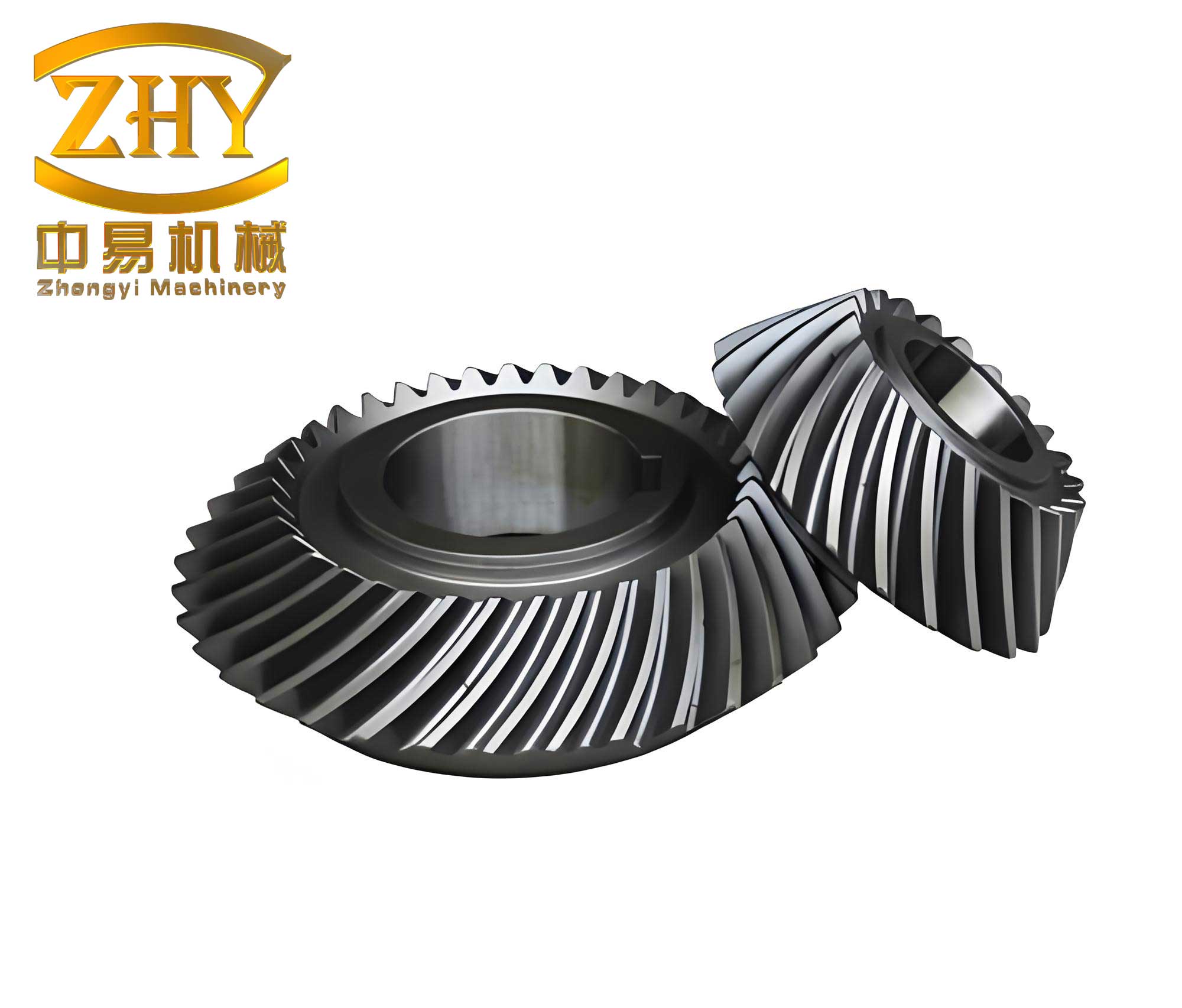
The image above showcases examples of spiral gears designed using this parametric approach. As seen, the teeth exhibit a smooth helical form, which is essential for reducing noise and vibration in motion transmission. This visual representation underscores the practical output of the methodology. Beyond mere modeling, parametric spiral gears serve as the foundation for advanced engineering analyses. For example, once the 3D model is established, it can be exported for finite element analysis (FEA) to assess stress distribution under load, or for computational fluid dynamics (CFD) to study lubrication patterns. Additionally, in manufacturing, the model can drive CNC programming for gear cutting or 3D printing, ensuring accuracy from design to production. The parametric nature means that any design iteration—say, adjusting the helix angle to optimize efficiency—can be propagated automatically through downstream processes.
To further elucidate the mathematical backbone, let’s explore the derivation of key formulas. The involute curve is fundamental to gear tooth geometry; it ensures constant velocity ratio and smooth engagement. In parametric form, the involute is derived from the base circle, where the arc length equals the tangent length. The equation in cylindrical coordinates (r, θ, z) is parameterized by t, which scales the involute angle. For a spiral gear, this curve is projected along a helix, introducing the helix angle β. The relationship between the linear advance along the axis (z) and the rotational angle (θ) is governed by the helix lead, given by:
$$\text{Lead} = 2\pi \cdot r_p \cdot \cot(\beta)$$
This lead determines how tightly the tooth winds around the gear. In the helix equation, the term $$\frac{360 \cdot b \cdot \tan(\beta)}{\pi \cdot 2 \cdot r_p}$$ converts the linear distance along face width into an angular displacement, ensuring the tooth follows a consistent spiral path. Another critical formula is the tooth thickness angle θ_b, which ensures proper meshing with mating gears. It is calculated from the base circle tooth thickness t_b, itself derived from the pitch circle tooth thickness t_p and the pressure angle α. The comprehensive set of equations, as listed in Table 1, forms a closed system that fully defines the spiral gear geometry. By encoding these in Pro/E Relations, the model becomes a dynamic entity responsive to input changes.
In practice, I have found that using tables to manage parameter sets enhances usability. For instance, Table 3 below provides sample input values for different types of spiral gears, ranging from low-helix to high-helix configurations. This table can be integrated into Pro/E as a design table or referenced via Program to automate variant generation. Such tabular data is invaluable for standardizing spiral gear designs across an organization.
| Spiral Gear Type | Module (m) mm | Number of Teeth (z) | Pressure Angle (α) degrees | Helix Angle (β) degrees | Face Width (b) mm | Typical Use Case |
|---|---|---|---|---|---|---|
| Light-Duty Helical | 1.5 | 20 | 20 | 10 | 15 | Small machinery, robotics |
| Medium-Duty Spiral Gear | 3.0 | 40 | 20 | 15 | 30 | Automotive transmissions |
| Heavy-Duty Helical | 5.0 | 60 | 20 | 20 | 50 | Industrial gearboxes |
| High-Speed Spiral Gear | 2.0 | 30 | 25 | 25 | 25 | Aerospace systems |
| Precision Spiral Gear | 1.0 | 50 | 14.5 | 5 | 10 | Watchmaking, instruments |
Implementing this parametric design for spiral gears has taught me several valuable lessons. First, planning the feature order in Pro/E is crucial to avoid parent-child dependency issues. I recommend creating the base geometry (e.g., the extruded blank) first, then adding curves and sweeps, and finally applying patterns and cuts. Second, extensive use of Relations ensures dimensional integrity, but it must be paired with clear variable naming. For example, I prefix parameters like “m” for module and “z” for tooth count to avoid conflicts. Third, the Program module’s conditional statements must be tested thoroughly, especially for edge cases like r_b = r_d. I developed a validation routine that checks all geometric constraints before regeneration, preventing model failure. These tips, combined with the detailed steps above, empower engineers to harness Pro/E for efficient spiral gear design.
Looking ahead, the parametric methodology for spiral gears can be extended to other gear types, such as bevel gears or worm gears, by adapting the equations and sweep paths. Moreover, integration with external software via Pro/E’s toolkit (Pro/TOOLKIT) could enable automated design optimization, where algorithms adjust parameters to minimize weight or maximize strength. The spiral gear, as a cornerstone of mechanical systems, benefits immensely from such digital tools. In my ongoing work, I am exploring cloud-based parameter databases that allow team collaboration on spiral gear designs, further pushing the boundaries of innovation.
In conclusion, the parametric design of spiral gears in Pro/E is a powerful technique that blends mathematical rigor with software proficiency. By leveraging equations for involutes and helices, along with Pro/E’s Program and Relation features, designers can create adaptable, accurate models that drive engineering success. The spiral gear, with its helical teeth, exemplifies the beauty of parametric modeling—where a single template can spawn countless variations. I encourage fellow engineers to experiment with this approach, refine the formulas, and share insights to advance the field. Whether for education, prototyping, or production, mastering parametric spiral gear design is a worthwhile investment in the future of mechanical engineering.