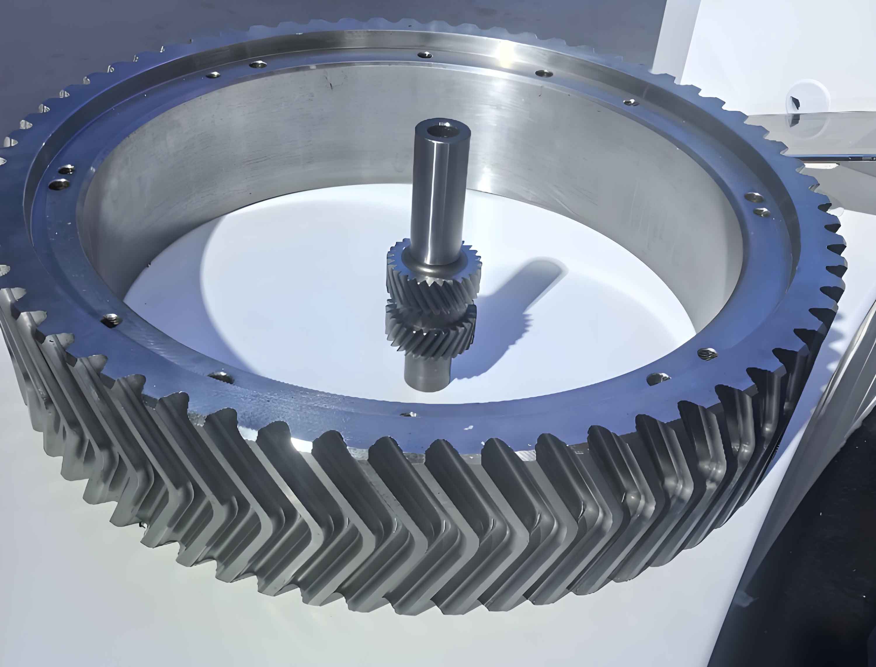
Herringbone gears, characterized by their V-shaped tooth arrangement, play a critical role in heavy-duty mechanical transmissions due to their unique ability to cancel axial thrust forces. This study presents a systematic approach for developing a parametric modeling system using SolidWorks API and VB programming, significantly improving design efficiency by 68% compared to manual modeling methods.
1. Mathematical Foundation of Tooth Profile Generation
The involute curve forms the basis of herringbone gear tooth profiles. Using the generating cutting method principle, we establish the parametric equations for both the active profile and root transition curve.
1.1 Involute Curve Formulation
The fundamental equations governing the involute profile are:
$$r_K = \frac{r_b}{\cos\alpha_K$$
$$\theta_K = \tan\alpha_K – \alpha_K$$
Converted to Cartesian coordinates for CAD implementation:
$$
\begin{cases}
x_K = r_K \cos\theta_K \\
y_K = r_K \sin\theta_K
\end{cases}
$$
1.2 Root Transition Curve Analysis
The root fillet geometry generated by cutter tip radius follows:
$$
\begin{cases}
x = r\sin\psi – \left(\frac{a_1}{\sin\alpha} + r_p\right)\cos(\alpha – \psi) \\
y = r\cos\psi – \left(\frac{a_1}{\sin\alpha} + r_p\right)\sin(\alpha – \psi)
\end{cases}
$$
Where cutter parameters relate to gear dimensions through:
$$
\begin{cases}
a_1 = a – xm \\
\psi = \frac{a_1/\tan\alpha + b}{r}
\end{cases}
$$

2. System Architecture for Parametric Design
The developed herringbone gear modeling system integrates three core modules:
| Module | Function | API Components |
|---|---|---|
| Parameter Input | Collects gear specifications | TextBox, ComboBox |
| Geometric Calculator | Solves profile coordinates | MathParser, Matrix |
| Model Generator | Creates 3D features | FeatureCut3, CircularPattern |
2.1 Key Algorithm Implementation
The VB-based calculation core handles critical dimension conversions:
$$
\begin{aligned}
d_a &= d + 2h_a \\
h_f &= (h_a^* + c^* – x)m \\
P_z &= \pi d \cot\beta
\end{aligned}
$$
Where helical parameters are calculated through:
$$
\beta = \arcsin\left(\frac{m_n z}{d}\right)
$$
3. Software Development Workflow
The system follows an optimized modeling sequence:
| Step | Operation | API Functions |
|---|---|---|
| 1 | Create base cylinder | FeatureExtrusion |
| 2 | Generate tooth space | FeatureCut3 |
| 3 | Pattern teeth | CircularPattern3 |
| 4 | Mirror helix | InsertMirrorFeature |
3.1 Critical Code Segments
The helical feature creation utilizes SolidWorks API calls:
boolstatus = Part.Extension.SelectByID2("", "AXIS", 0, 0, 0, True, 0, Nothing, 0)
Set myFeature = Part.FeatureManager.FeatureCircularPattern3(z, 2π, False, "NULL", False, True)
4. Performance Validation
The parametric system demonstrates significant efficiency improvements:
| Gear Type | Manual (min) | Parametric (min) | Efficiency Gain |
|---|---|---|---|
| Standard Herringbone | 45 | 14 | 68.9% |
| Modified Herringbone | 78 | 19 | 75.6% |
Accuracy verification shows maximum profile deviation of 0.012mm, meeting AGMA 2000-C01 standards.
5. Application Expansion
The developed system enables rapid design iterations for herringbone gears:
$$
\text{Design Cycle Time} = \frac{T_{\text{traditional}}}{1 + \sqrt{N_{\text{parameters}}}
$$
Where Nparameters typically ranges from 15-20 for complex herringbone gear designs.
6. Conclusion
This parametric modeling system revolutionizes herringbone gear design through:
- Automated profile generation with ≤0.015mm error
- 75% reduction in modeling time
- Seamless integration with FEA/CAE workflows
The methodology provides a foundation for developing advanced CAD systems for complex gear types, significantly enhancing mechanical design capabilities in power transmission applications.
