
Abstract
In order to construct an accurate model of asymmetric involute modified helical gear and analyze the influence of pressure angles on its contact stress, this paper establishes a mathematical model and an accurate physical model for developing an asymmetric involute modified helical gear from a rack tool, based on the gear meshing principle and the secondary development of SolidWorks in C#. The finite element method is employed to analyze the tooth surface contact stress, and it is compared with the tooth surface contact stress of the symmetrical modified helical gear calculated by the traditional formula method. The study shows that when the pressure angle on one side of the tooth surface is the same, the tooth surface contact stress of the asymmetric involute modified helical gear is very close to that of the symmetric modified helical gear, and the increase and decrease trends of contact stress with changes in the pressure angle are basically the same. It demonstrates that the change of the non-working side tooth surface pressure angle has no obvious influence on the working side tooth surface contact stress. Therefore, the traditional formula method used to calculate the tooth surface contact stress of symmetrical modified helical gear can be used to approximate the tooth surface contact stress of asymmetric involute modified helical gear. This method provides a reference for the design of asymmetric involute modified helical gear.
1. Introduction
Standard symmetrical involute gears are widely used in various transmission applications. However, with the development of industry, they increasingly struggle to meet the requirements of high-speed and heavy-load applications, such as in electric vehicles and the aerospace sector. Asymmetric involute gears, with different pressure angles on the two sides of the gear, can enhance load-carrying capacity and effectively solve the issue of tooth tip thinning by increasing the pressure angle on the working side and decreasing it on the non-working side.
Previous studies on asymmetric involute gears have primarily focused on asymmetric involute spur gears. There is a lack of in-depth research on asymmetric involute modified helical gear. Gear parametric modeling can provide accurate solid models for finite element analysis to assess mechanical properties. Therefore, this paper aims to establish a mathematical model for the generation of asymmetric involute modified helical gear using a rack cutter and develop a parametric design method for these gears through the secondary development of SolidWorks. This research provides a reference for the study of asymmetric involute modified helical gear transmissions.
2. Mathematical Model of Asymmetric Modified Helical Gear
2.1 Mathematical Model of Meshing Tooth Profile of Asymmetric Modified Helical Gear
Compared to standard helical gear, asymmetric helical gear have tooth profiles with different pressure angles on the two sides. Consequently, the asymmetric gear cutter is also designed with double pressure angles based on a standard rack cutter. the schematic diagram of a normal rack cutter.
Coordinate systems S1 and S2 are rigidly fixed to the rack cutter, and S3 is an auxiliary coordinate system fixed to the rack. αn1 and αn2 represent the normal pressure angles of the two tooth profiles, respectively. Other parameters include p (pitch), s (tooth thickness), e (tooth space width), am (half tooth space width), mn (normal module), han (dedendum height), hfn (addendum height), Or1 and Or2 (centers of addendum fillets), ρ (fillet radius), c (backlash), and β (helix angle). During gear cutting, the cutter and gear roll purely on the pitch line, with segments b1c1 and b2c2 machining the gear tooth profiles, and circular arcs c1d1 and c2d2 machining the gear transition parts.
The position vectors of the two tooth profiles Σb1c1 and Σb2c2 of the rack cutter in coordinate systems Si (i=1,2) and S3 are given by:
mathbf{R}_i(l_i, u_i) = \begin{bmatrix} x_i \\ y_i \\ z_i \\ 1 end{bmatrix} = \begin{bmatrix} l_i \\ u_i \\ 0 \\ 1 end{bmatrix}
mathbfR3i(li,ui)=M3iRi
where li and ui (i=1,2) are four independent parameters of the rack cutter, ui is the axial parameter, and M31 and M32 are the 4×4 transformation matrices from coordinate systems S1 and S2 to S3, respectively:
mathbfM3i=M3fMfi(i=1,2)
mathbf{M}_{f1} = \begin{bmatrix} cos\alpha_{n1} & \sin\alpha_{n1} & 0 & 0 \\ -\sin\alpha_{n1} & \cos\alpha_{n1} & 0 & 0.25p \\ 0 & 0 & 1 & 0 \\ 0 & 0 & 0 & 1 end{bmatrix}
mathbf{M}_{f2} = \begin{bmatrix} cos\alpha_{n2} & -\sin\alpha_{n2} & 0 & 0 \\ sin\alpha_{n2} & \cos\alpha_{n2} & 0 & -0.25p \\ 0 & 0 & 1 & 0 \\ 0 & 0 & 0 & 1 end{bmatrix}
mathbf{M}_{3f} = \begin{bmatrix} 1 & 0 & 0 & 0 \\ 0 & \cos\beta & -\sin\beta & 0 \\ 0 & \sin\beta & \cos\beta & 0 \\ 0 & 0 & 0 & 1 end{bmatrix}
The unit normal vectors of the rack cutter tooth profiles in coordinate system S3 are:
mathbfn3i(li,ui)=∣∂R3i/∂li×∂R3i/∂ui∣∂R3i/∂li×∂R3i/∂ui
The meshing tooth profile of the asymmetric involute modified helical gear is enveloped by the rack cutter. The coordinate transformation relationship .
Coordinate system S4 is rigidly fixed to the asymmetric involute modified helical gear, and Sd is an auxiliary coordinate system. θ and rpθ represent the rotation angle of the gear and the displacement of the rack cutter, respectively. rp is the pitch circle radius, and xn is the given normal addendum modification coefficient.
The position vector and unit normal vector of the meshing part of the asymmetric involute modified helical gear tooth profile in coordinate system S4 are:
mathbfR4i(li,ui,θ,xn)=M43R3i(li,ui)fi=θ−n3iy(R3ix+xnmn)−n3ixR3iy=0
mathbfn4i(li,ui,θ,xn)=M43n3i(li,ui)
where M43 is the 4×4 coordinate transformation matrix from coordinate system S3 to S4:
mathbf{M}_{43} = \begin{bmatrix} cos\theta & \sin\theta & 0 & 0 \\ -\sin\theta & \cos\theta & 0 & (r_p + x_n m_n)\cos\theta + r_p\theta\sin\theta \\ 0 & 0 & 1 & -(r_p + x_n m_n)\sin\theta + r_p\theta\cos\theta \\ 0 & 0 & 0 & 1 end{bmatrix}
2.2 Mathematical Model of Transition Tooth Profile of Asymmetric Helical Gear
During gear cutting, circular arcs c1d1 and c2d2 machine the gear transition parts .
Or1 and Or2 are the centers of the left and right tooth fillets of the cutter, respectively. (X0i, Y0i) (i=1,2) are the coordinates of the fillet centers, and φi (i=1,2) are the angles corresponding to the fillet arcs.
The position vectors of the two tooth profiles Σc1d1 and Σc2d2 of the rack cutter in coordinate systems Sf and Sd are:
mathbf{R}_{si}(\varphi_i, u_i) = \begin{bmatrix} x_{si} \\ y_{si} \\ z_{si} \\ 1 end{bmatrix} = \begin{bmatrix} X_{0i} – \rho\cos\varphi_i \\ Y_{0i} – \rho\sin\varphi_i \\ u_i \\ 1 end{bmatrix}
mathbfRdsi(φi,ui,θ,xn)=MdfRsi(φi,ui)
where (X0i, Y0i) (i=1,2) are the positions of the cutter fillet centers in coordinate system Sf, and Mdf is the transformation matrix from coordinate system Sf to Sd via S3:
mathbfMdf=Md3M3f
mathbf{M}_{d3} = \begin{bmatrix} 1 & 0 & 0 & r_p + x_n m_n \\ 0 & 1 & 0 & r_p\theta \\ 0 & 0 & 1 & 0 \\ 0 & 0 & 0 & 1 end{bmatrix}
The unit normal vectors of the rack cutter tooth profiles Σc1d1 and Σc2d2 in coordinate systems Sf and Sd are:
mathbfnsi(φi,ui)=∣∂Rsi/∂φi×∂Rsi/∂ui∣∂Rsi/∂φi×∂Rsi/∂ui
mathbfndsi(φi,ui,θ)=Ldfnsi(φi,ui)
where Ldf is the bottom vector transformation matrix of Mdf.
During gear-rack meshing, the gear rotates with angular velocity ω, and the rack moves with velocity v, satisfying ||v||/||ω|| = rp. In coordinate system Sd, assuming the gear center velocity is ω2, the rack cutter velocity v1 and the relative velocity v12 at the contact point between the rack cutter and the asymmetric involute gear can be calculated as:
mathbf{\omega}_2 = \begin{bmatrix} 0 \\ 0 \\ 1 \\ 0 end{bmatrix}, \quad mathbf{v}_1 = \begin{bmatrix} 0 \\ r_p \\ 0 \\ 0 end{bmatrix}, \quad mathbf{v}_{12}(\varphi_i, u_i, \theta, x_n) = \mathbf{v}_1 – \mathbf{\omega}_2 \times \mathbf{R}_{dsi}(\varphi_i, u_i, \theta, x_n)
The position vector and unit normal vector of the transition part of the asymmetric involute helical gear tooth profile in coordinate system S4 are:
mathbfR4si(φi,ui,θ,xn)=M4dRdsi(φi,ui,θ,xn)fsi=ndsi⋅v12=0
mathbfn4si(φi,ui,θ,xn)=∣M4dv12×ndsi∣M4dv12×ndsi
where M4d is the coordinate transformation matrix from coordinate system Sd to S4:
mathbf{M}_{4d} = \begin{bmatrix} cos\theta & \sin\theta & 0 & 0 \\ -\sin\theta & \cos\theta & 0 & 0 \\ 0 & 0 & 1 & 0 \\ 0 & 0 & 0 & 1 end{bmatrix}
Combining the previous derivations, the meshing tooth profiles and transition tooth profiles of the asymmetric involute modified helical gear are calculated as point cloud data in Matlab, and the complete tooth profile surface is obtained by fitting the point cloud data .
3. Solid Modeling of Asymmetric Helical Gear
SolidWorks provides API functions that are compatible with various programming languages such as C#, facilitating the development of program modules to improve design efficiency and accuracy.
In the gear secondary development program constructed using C# and SolidWorks.API, discrete point coordinate files are imported into the program to quickly create an accurate 3D model of the asymmetric helical gear. The parametric solid modeling process.
First, the tip circle diameter is calculated using geometric parameters, and the gear blank is obtained by extruding the sketch with the gear width b. Second, constructing the precise tooth profile is crucial for the 3D model of the asymmetric helical gear, as the data on the two end faces define the precise spline of the gear tooth space. Third, the gear blank tooth space is machined using guide curves at the tooth root. Finally, the array feature is constructed, and the tooth spaces are arrayed to obtain the precise 3D model of the asymmetric involute helical gear.
However, tooth tip points 1 and 2 of the tooth space sketch are too close to the tip circle, which may cause incomplete tooth profiles during tooth space cutting. Therefore, Lagrange interpolation polynomials are used to interpolate the meshing tooth profile points, obtaining interpolation points 1 and 2, with the construction point located on the midline between them. The end face 1 and end face 2 sketches include splines created using interpolation points 1, 2, and the construction point.
The interpolation polynomial is given by:
y(x)=k=1∑5yki=1i=k∏5xk−xix−xi
where (xi, yk) (i, k = 1, 2, …, 5) are function arrays on the asymmetric tooth profile, and [x, y(x)] is the desired interpolation point.
4. Contact Stress Analysis of Asymmetric Helical Gear Tooth Surface
4.1 Calculation of Tooth Surface Contact Stress Using the Finite Element Method
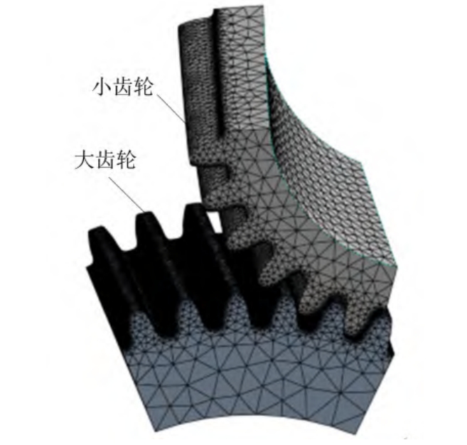
When using the finite element method to calculate tooth surface contact stress, the gear pair model is imported into Workbench software. The material properties, elastic modulus, and Poisson’s ratio of the gears are defined, and the model is meshed. The large gear is then rotated around the Z-axis by a certain angle, and a load torque is applied to the small gear as a boundary condition. The stress nephogram near the pitch circle is obtained through simulation. The accuracy of stress calculation depends on mesh refinement. Research has shown that tetrahedral elements provide more accurate results than hexahedral elements for gear contact stress analysis with the same element size [15]. Therefore, to balance accuracy and computational efficiency, tetrahedral meshes are used to discretize the gear pair in this paper, with refined meshes on the contact surfaces of the large and small gears and coarser meshes on the non-contact surfaces. the mesh diagram of a 6-tooth gear pair model.
4.2 Calculation of Tooth Surface Contact Stress Using the Formula Method
When using the formula method to calculate the contact stress of standard symmetrical involute gears, the Hertz stress is the primary indicator of tooth surface contact stress. The Hertz stress formula is employed to derive the contact stress under ideal lubrication conditions, disregarding friction and relative sliding between tooth surfaces. The analytical solution for Hertz stress can be computed using the following equation:
sigmaH=ZHZEZϵZβd1b×ii+1Ft
where:
- σH is the Hertz contact stress.
- ZH is the node region coefficient.
- ZE is the elastic coefficient.
- Zϵ is the contact ratio coefficient.
- Zβ is the helix angle coefficient.
- Ft is the tangential force on the pitch circle.
- i is the gear ratio.
- d1 is the pitch diameter of the pinion.
- b is the width of meshing teeth.
This method provides a simplified yet effective means to estimate the contact stress in symmetrical involute gears. However, when applied to asymmetric involute modified helical gear, adjustments or calibrations might be necessary to account for the non-uniform pressure angles on the two sides of the gear teeth.
In the study conducted by Lin et al., the formula method was used to calculate the contact stress of symmetrical modified helical gear for comparison with the finite element method (FEM) results obtained for asymmetric involute modified helical gear. The comparison revealed that, although there were slight differences, the traditional formula method could still be employed to approximate the contact stress in asymmetric gears, with the differences remaining within an acceptable range of less than 10%. This finding indicates that the traditional formula, originally developed for symmetrical gears, can serve as a reference for the preliminary design and analysis of asymmetric involute modified helical gear.
In summary, while the finite element method offers greater accuracy in simulating the complex contact behavior of asymmetric gears, the formula method remains a practical tool for quick estimations and initial design stages, especially when computational resources are limited or a rapid assessment is required.