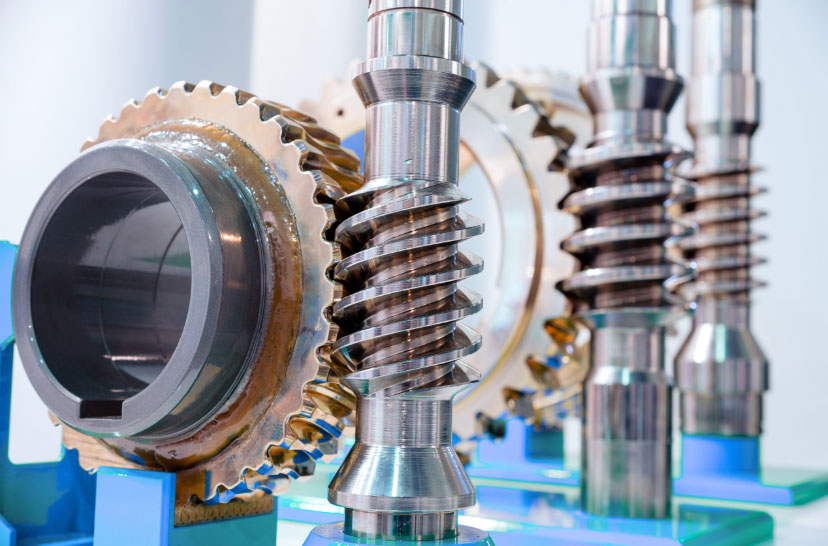
Worm gears serve as critical components in aviation Auxiliary Power Unit (APU) systems, requiring precise modeling and rigorous performance validation. This study investigates parametric design methodologies, contact stress characteristics, thermal behavior, and dynamic responses of worm gear systems under operational conditions.
1. Parametric Modeling Methodology
The mathematical foundation for worm gear modeling derives from spatial meshing principles and coordinate transformation theory. The parametric equations for tooth profiles are established through kinematic analysis of the worm-wheel interaction:
$$
\begin{cases}
x = l \cos \alpha_k \cos \theta \\
y = l \cos \alpha_k \sin \theta \\
z = -l \sin \alpha_k + p\theta
\end{cases}
$$
where $l$ represents the cutting tool displacement, $\alpha_k$ denotes the pressure angle, and $p$ signifies the helical parameter. The coordinate transformation matrix between worm and gear coordinate systems is expressed as:
$$
M_{12} = \begin{bmatrix}
\cos \phi_1 \cos \phi_2 & -\cos \phi_1 \sin \phi_2 & \sin \phi_1 & a \cos \phi_1 \\
\sin \phi_1 \cos \phi_2 & -\sin \phi_1 \sin \phi_2 & -\cos \phi_1 & a \sin \phi_1 \\
\sin \phi_2 & \cos \phi_2 & 0 & 0 \\
0 & 0 & 0 & 1
\end{bmatrix}
$$

2. Contact Stress Analysis
Finite element analysis reveals significant differences in contact performance between steel-steel and bronze-steel worm gear pairs:
| Loading Condition | Steel-Steel (MPa) | Bronze-Steel (MPa) |
|---|---|---|
| Intake Drive (4级强风) | 1113.36 | 982.63 |
| Exhaust Drive (4级强风) | 927.84 | 810.29 |
| Intake Locking (4级强风) | 1420.46 | 1257.79 |
The Hertzian contact stress formula validates simulation results with <8% deviation:
$$
\sigma_H = Z_E \sqrt{\frac{F_n}{\rho_{\Sigma} L}}
$$
where $Z_E$ represents material elasticity coefficient, $F_n$ denotes normal load, and $\rho_{\Sigma}$ signifies comprehensive curvature radius.
3. Thermal Behavior Evaluation
The thermal network model considers both bulk temperature and flash temperature components:
$$
\begin{cases}
q = \beta \alpha f P_n v_s / b \\
T_{max} = \frac{3\mu w_d(v_1 – v_2)}{4\pi b_H} \sqrt{\frac{2b_H}{\lambda \rho c v}}
\end{cases}
$$
Key thermal parameters for 0Cr17Ni4Cu4Nb steel worm gears include:
| Parameter | Value |
|---|---|
| Thermal Conductivity | 15.9 W/m·K |
| Specific Heat Capacity | 502 J/kg·K |
| Maximum Bulk Temperature | 36.8°C |
| Peak Flash Temperature | 60.7°C |
4. Dynamic Characteristics
Modal analysis confirms the structural integrity of worm gear shafts under operational vibrations:
$$
\begin{bmatrix}
M
\end{bmatrix} \{\ddot{x}\} +
\begin{bmatrix}
C
\end{bmatrix} \{\dot{x}\} +
\begin{bmatrix}
K
\end{bmatrix} \{x\} = \{F\}
$$
Natural frequency analysis reveals sufficient margin from excitation frequencies:
| Mode | Frequency (Hz) |
|---|---|
| 1st | 637.23 |
| 3rd | 1683.8 |
| 6th | 3542.7 |
| 10th | 7225.5 |
5. Advanced Manufacturing Considerations
The parametric modeling plugin incorporates design constraints for aviation applications:
$$
\begin{cases}
q = \frac{d_1}{m} \geq 8 \\
z_2 \geq 28 \left(1 – \frac{q – 8}{25}\right)
\end{cases}
$$
Optimization algorithms enable rapid configuration of worm gear parameters while maintaining:
- Contact ratio > 1.25
- Sliding velocity < 15 m/s
- Bending safety factor > 2.0
This comprehensive analysis methodology provides critical insights for designing high-reliability worm gear systems in aerospace applications, particularly for APU actuation mechanisms requiring compact dimensions and high load capacity.
