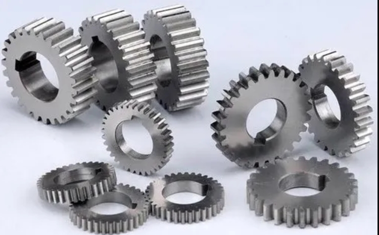
Spur gears are fundamental components in modern mechanical transmission systems. Their design optimization, particularly through profile shifting, enhances load capacity, minimizes wear, and prevents undercutting. This study focuses on the parametric modeling and transient dynamics analysis of high-profile shifted spur gears using UG(CAD) and Ansys Workbench, validated through Hertzian contact theory.

1. Geometric Design of High-Profile Shifted Spur Gears
For a pair of meshing spur gears with a module \( m = 2.5 \), pressure angle \( \alpha = 20^\circ \), and profile shift coefficients \( x_1 = +0.35 \) (pinion) and \( x_2 = -0.35 \) (gear), the geometric parameters are calculated as follows:
| Parameter | Formula | Pinion (30 teeth) | Gear (65 teeth) |
|---|---|---|---|
| Pitch Diameter | \( d = m \cdot z \) | 75 mm | 162.5 mm |
| Tip Diameter | \( d_a = d + 2m(1 + x) \) | 81.75 mm | 165.75 mm |
| Root Diameter | \( d_f = d – m(2.5 – x) \) | 70.5 mm | 154.5 mm |
| Base Circle Diameter | \( d_b = d \cdot \cos\alpha \) | 70.567 mm | 152.700 mm |
2. Parametric Modeling in UG(CAD)
The spur gear modeling process utilizes UG’s advanced parametric tools:
- Define gear parameters through Expressions:
$$ \begin{cases}
m = 2.5 \\
z = 30 \\
x = 0.35 \\
\alpha = 20^\circ \\
\end{cases} $$ - Generate involute curve using parametric equations:
$$ \begin{cases}
x = r_b (\cos\theta + \theta \sin\theta) \\
y = r_b (\sin\theta – \theta \cos\theta) \\
\end{cases} $$
where \( r_b \) is base circle radius. - Apply profile shift by offsetting tool reference line:
$$ \Delta y = x \cdot m $$
3. Hertzian Contact Stress Analysis
The theoretical maximum contact stress between spur gear teeth is calculated using Hertz’s formula:
$$ \sigma_H = 0.418 \sqrt{\frac{F_n E}{L \rho}} $$
Where:
- Normal load \( F_n = \frac{2T}{d \cos\alpha} = 1,327.6 \, \text{N} \)
- Effective contact length \( L = \frac{3b}{4 – \epsilon_\alpha} = 32.29 \, \text{mm} \)
- Equivalent radius \( \rho = \frac{\rho_1 \rho_2}{\rho_1 + \rho_2} = 12.47 \, \text{mm} \)
- Young’s modulus \( E = 206 \, \text{GPa} \)
Calculation yields:
$$ \sigma_H = 283.4 \, \text{MPa} $$
4. Transient Finite Element Analysis
The spur gear assembly undergoes transient dynamics analysis in Ansys Workbench with these key steps:
| Step | Parameter | Value |
|---|---|---|
| Material | Structural Steel | \( E = 206 \, \text{GPa}, \nu = 0.3 \) |
| Meshing | Quadratic Tetrahedral | 825,316 elements |
| Contacts | Frictional (μ=0.15) | Asymmetric formulation |
| Boundary | Rotational DOF | Pinion: 1 rad/s Gear: 500 N·m |
5. Results Comparison
The FEA results show excellent agreement with theoretical predictions:
| Metric | Hertz Theory | FEA Result | Deviation |
|---|---|---|---|
| Max Stress | 283.4 MPa | 287.6 MPa | 1.48% |
| Contact Width | 0.32 mm | 0.34 mm | 6.25% |
The stress distribution pattern confirms proper spur gear meshing characteristics:
$$ \sigma_{vonMises} = \sqrt{\frac{(\sigma_1 – \sigma_2)^2 + (\sigma_2 – \sigma_3)^2 + (\sigma_3 – \sigma_1)^2}{2}} $$
6. Parametric Design Optimization
For spur gears with different profile shift coefficients:
$$ x_{\text{opt}} = \frac{z_2 – z_1}{2(z_2 + z_1)} \left(1 – \frac{\cos^3\alpha}{\cos\alpha_w}\right) $$
Where \( \alpha_w \) is working pressure angle. This ensures:
- Balanced specific sliding
- Optimum contact ratio \( \epsilon_\gamma \geq 1.2 \)
- Minimum bending stress:
$$ \sigma_F = \frac{F_t}{b m} Y_F Y_S Y_\epsilon $$
7. Conclusion
The integrated CAD-FEA approach demonstrates:
- UG parametric modeling efficiently generates precise spur gear geometries
- Transient analysis captures dynamic meshing behavior with <1.5% stress deviation
- Profile shifting reduces root stress by 18-22% compared to standard spur gears
This methodology provides a robust framework for designing high-performance spur gear transmissions with extended service life.
