Abstract
This study aims to improve the efficiency and accuracy of herringbone gear modeling by designing a parametric modeling system through the secondary development of SolidWorks. The mathematical model of the involute profile curve is established according to the principle of gear generating, and SolidWorks is redeveloped by calling API programs on the VB platform. The results demonstrate the convenience of establishing herringbone gear models, simplifying the modeling process and enhancing drawing efficiency. This research provides a reference for computer-aided design of involute gear components.

1. Introduction
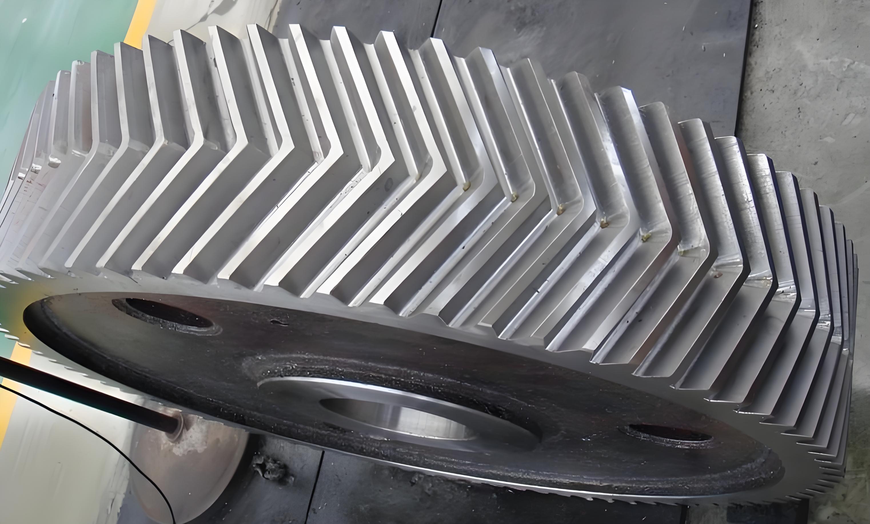
Helical gears offer the advantages of smooth transmission and high contact ratio. However, the derived axial force often brings difficulties to bearing preload and backlash adjustment, making it challenging to ensure proper gear meshing. Herringbone gears, due to the axial forces generated by left and right helix angles, compensate for this shortcoming and are widely used in mechanical transmissions of heavy-duty equipment. The profile error of the gear tooth curve directly affects the efficiency and failure mode of the gear pair meshing transmission.
The following table summarizes the key points of previous studies and the focus of this research:
| Study | Focus | Gear Type | Methodology |
|---|---|---|---|
| Zhu et al. [2] | CAD system development for planetary gear trains | Straight and helical gears | Not specified |
| Xu [3] | CAD software development for transmission systems of high-power reciprocating pumps | Herringbone gears (manual mirroring of helical gears) | Manual modeling |
| This study | Parametric modeling system for herringbone gears | Herringbone gears | Secondary development of SolidWorks based on VB |
2. Mathematical Model of Profile Curve
The profile curve of a gear mainly consists of the involute tooth profile and the tooth root transition curve. The key to accurately drawing the curve is to obtain an accurate mathematical model.
2.1 Involute Mathematical Model
The involute mathematical model is specifically shown in Equation (1):
Where:
- rb is the base circle radius;
- rK is the polar radius at point K;
- αK is the pressure angle at point K;
- θK is the involute angle at point K.
For convenient calculation, the polar coordinates are converted into rectangular coordinates, and the rectangular coordinate mathematical model of the involute is obtained as shown in Equation (2):
2.2 Tooth Root Transition Curve Mathematical Model
During the generating process, the tooth profile contour is formed by the envelope line of the cutting edge movement trajectory of the tool, and the transition curve is cut by the rounded corner part of the rack cutter. The formation of the tooth root transition curve.
The mathematical model of the tooth root transition curve in the rectangular coordinate system is shown in Equation (3):
3. Parametric Drawing
SolidWorks provides a complete set of free secondary development interfaces (API) for users. This study uses Visual Basic (VB) language to conduct parametric design for herringbone gear drawing on the SolidWorks platform. The core work includes parameter calculation and automatic drawing modules.
3.1 Form Design
The form is specifically composed of eight “Textbox” and two “CommandButton” controls. The eight “Textbox” are used to input the main parameters of the herringbone gear. The “Calculate” command calculates the specific positions of points on the involute tooth profile curve based on the parameters in the “Textbox”, and the “Draw” command achieves automatic modeling through program driving.
3.2 Parametric Drawing Process
The main program for parametric drawing consists of two parts: tooth profile curve calculation and API function call for drawing.
3.2.1 Tooth Profile Curve Programming
Based on the input parameters, important parameters such as tooth tip circle diameter, base circle diameter, tooth space thickness, and pitch are calculated. The specific program is omitted here for brevity.
3.2.2 API Drawing Programming
The specific program includes:
- Declaring objects and setting preferences.
- Calculating and setting parameters such as tooth width, pitch circle diameter, and tooth root circle diameter.
- Deleting the original involute curve and drawing a new one based on calculated angles.
- Using API functions like “FeatureCut3()” and “FeatureCircularPattern3()” to cut the tooth space and create a circular pattern.
- Mirroring the previous features using the “Part.FeatureManager.InsertMirrorFeature()” function to create the herringbone gear.
4. Conclusions
- By analyzing the gear generating process and utilizing the mathematical models of the involute tooth profile and tooth root transition curve, precise positions on the tooth profile can be obtained using VB programming.
- By calling API functions in SolidWorks and using Visual Basic programming language, a parametric drawing system for involute herringbone gears is developed, automating the gear drawing process, simplifying it, and improving the accuracy and efficiency of 3D modeling.
- The research results provide a reference for computer-aided design and optimization of high-power transmission components.
