
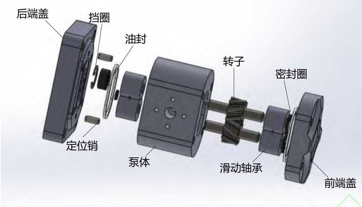
The physical model of a double arc helical gear pump can be described in terms of its key components and their interactions. The primary components of a double arc helical gear pump are:
- Housing: The housing contains and supports all the other components, providing a sealed environment for the fluid and the gear mechanism. It has an inlet and an outlet for fluid flow.
- Rotor assembly: The rotor assembly consists of a pair of meshing double arc helical gears, one of which is the driving gear (connected to the power source) and the other is the driven gear. These gears have a unique tooth profile, which improves the meshing, reduces wear, and minimizes noise.
- Bearings and seals: Bearings support the rotor assembly and ensure smooth rotation, while seals maintain the integrity of the pump by preventing fluid leakage.
- Inlet and outlet ports: The inlet port is where the fluid enters the pump, and the outlet port is where the fluid exits the pump. The design of these ports and their positioning in the housing is crucial to ensure proper fluid flow and to minimize pressure losses.
The operation of a double arc helical gear pump can be described in the following steps:
- As the driving gear rotates, it meshes with the driven gear, creating a series of expanding and contracting volumes between the gear teeth.
- During the suction phase, the expanding volume between the meshing teeth draws fluid into the pump through the inlet port.
- The fluid is then trapped between the gear teeth and the housing, creating a sealing effect.
- As the gears continue to rotate, the contracting volume between the meshing teeth forces the fluid out of the pump through the outlet port.
- The cycle repeats, providing continuous fluid flow.
To create a physical model of a double arc helical gear pump, a combination of engineering principles, such as gear design, fluid mechanics, and structural analysis, must be applied. Additionally, the pump’s performance can be optimized by considering factors such as gear tooth profile, rotor clearances, and housing geometry. Computational tools, such as computational fluid dynamics (CFD) and finite element analysis (FEA), can be used to analyze and optimize the design before manufacturing a physical prototype.