
In my work, I investigated the machining and maintenance process of pinion gears used in locomotive bogies. The pinion gear shaft is a critical component in the drive unit because it transmits torque from the traction motor to the driven gear while also carrying combined bending, torsion, and contact loads. A stable interference fit between the pinion gear shaft bearing seats and the bearing inner rings is essential for the reliable operation of both the bearings and the pinion gears. During a high-level maintenance inspection, I found that the bearing seats on some pinion gear shafts had increased in diameter by approximately 0.01 mm to 0.12 mm. This abnormal growth was observed on both domestic and imported pinion gears. Because an excessive interference fit can reduce bearing internal clearance, distort raceways, increase stress, and even cause inner-ring cracking, I focused on two questions: what caused the bearing seat growth in these pinion gears, and how can I determine whether an already grown pinion gear shaft can be reused?
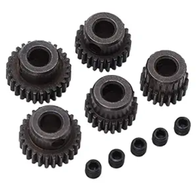
Background and Motivation
Railway transportation has become one of the most important freight and passenger transport modes because it offers high efficiency, relatively low cost, and large carrying capacity. The drive unit in a locomotive bogie is responsible for converting the high-speed, low-torque output of the traction motor into the low-speed, high-torque motion required by the wheelset. Pinion gears are a central part of this drive unit. They operate under alternating loads, vibration, impact, high-cycle fatigue, fretting wear, and temperature variation. In many previous studies, attention has been given mainly to tooth contact, gear meshing, tooth root strength, and profile modification, while the bearing seat and its interference fit with the bearing inner ring have received less attention. My investigation addresses this gap by linking heat treatment, residual stress, phase transformation, and interference-fit behavior in pinion gears.
The abnormal bearing seat growth is not merely a dimensional issue. When the bearing seat diameter increases, the effective interference with a new bearing inner ring also increases. The inner ring expands more than intended, which reduces the residual radial clearance. If the clearance becomes too small or negative, the rolling elements may become preloaded, the contact ellipse may change, friction and temperature may rise, and the fatigue life of the bearing may decrease. In severe cases, the inner ring may crack, causing the drive unit to fail. Therefore, I treated the dimensional stability of pinion gears as a safety-related and cost-related problem.
Technical Context and Literature Perspective
I reviewed two broad technical areas: heat treatment of precision shafts and interference-fit mechanics. Heat treatment is a special process because it does not visibly change the external shape of a workpiece in the same way as turning or milling, yet it controls phase composition, hardness, residual stress, and dimensional stability. For pinion gears, carburizing, quenching, and low-temperature tempering are typically used to obtain a hard, wear-resistant surface and a tough core. If the heat treatment is not properly controlled, retained austenite can remain in the microstructure. Retained austenite may transform later under service loads or temperature changes, causing local volume expansion and dimensional instability. This is especially important for pinion gears because their bearing seats require tight tolerances.
Interference-fit research has shown that the contact pressure, hub stress, shaft stress, and relative slip depend on the nominal interference, surface roughness, geometry, material properties, and temperature. Early analytical work used thick-walled cylinder theory. Later studies used finite element analysis to capture plasticity, contact nonlinearity, and thermal effects. For pinion gears, the interference fit must be high enough to prevent slipping under torque but not so high that the bearing inner ring yields or the clearance disappears. Table 1 summarizes the technical themes I considered.
| Theme | Key issue | Relevance to pinion gears |
|---|---|---|
| Quenching and tempering | Phase transformation, thermal stress, residual stress | Controls dimensional stability of pinion gears |
| Retained austenite | Volume expansion during martensite or bainite transformation | Can enlarge bearing seats on pinion gears during service |
| Interference fit | Contact pressure, inner-ring expansion, clearance loss | Determines whether pinion gears can be reused |
| Finite element simulation | Coupled temperature-displacement and contact analysis | Predicts stress and deformation in pinion gears |
| Automation | Post-processing, data extraction, pass/fail visualization | Improves maintenance efficiency for many pinion gears |
Heat Treatment Process and Finite Element Model of Pinion Gears
The pinion gears I studied were made of 17Cr2Ni2Mo, a low-carbon alloy steel commonly used for surface-hardened shafts and gears. The chemical composition is given in Table 2. The heat treatment route consisted of heating to about 820 °C, holding for approximately two hours, quenching in oil at a temperature not exceeding 60 °C, and then performing two low-temperature tempering treatments at about 180 °C for two hours each, followed by air cooling. I modeled the entire process to determine whether thermal stress alone could explain the abnormal bearing seat growth.
| Element | C | Cu | Mn | S | P | Cr | Ni | Mo | Si |
|---|---|---|---|---|---|---|---|---|---|
| Mass fraction (%) | 0.17 | 0.30 | 0.45 | 0.0035 | 0.0035 | 1.65 | 1.55 | 0.30 | 0.035 |
For the transient thermal analysis, I used the heat conduction equation:
$$ \rho c_p \frac{\partial T}{\partial t} = \nabla \cdot (k \nabla T) + \dot{q} $$
where \(\rho\) is density, \(c_p\) is specific heat capacity, \(T\) is temperature, \(t\) is time, \(k\) is thermal conductivity, and \(\dot{q}\) is the internal heat generation rate. The heat exchange between the pinion gear surface and the quenching oil was described by:
$$ q = h (T_s – T_\infty) $$
where \(q\) is heat flux, \(h\) is the heat transfer coefficient, \(T_s\) is the surface temperature, and \(T_\infty\) is the quenching oil temperature. Because \(h\) varies strongly with temperature, I used a temperature-dependent heat transfer coefficient curve for 17Cr2Ni2Mo and quenching oil.
I simplified the end teeth, main teeth, and threaded regions of the pinion gear shaft to reduce computational cost while preserving the bearing seat geometry. The mesh used hexahedral elements, a neutral-axis algorithm for the revolved body, a global size of 10, minimized mesh transition, and linear geometric order. The completed model contained 16,332 elements and 17,695 nodes. A fully coupled temperature-displacement transient analysis was used for quenching, while the tempering steps were evaluated for thermal stress evolution. I constrained the non-end-tooth face and applied gravity to approximate the actual handling condition.
| Model parameter | Value or setting |
|---|---|
| Material | 17Cr2Ni2Mo |
| Initial temperature for quenching | 820 °C |
| Quenching medium | Oil, not exceeding 60 °C |
| Quenching duration | 1600 s |
| Tempering temperature | 180 °C |
| Tempering time | 2 h per cycle |
| Number of tempering cycles | 2 |
| Element type | Hexahedral, linear |
| Number of elements | 16,332 |
| Number of nodes | 17,695 |
Quenching and Tempering Results for Pinion Gears
I extracted temperature and stress histories at the end-tooth side and the non-end-tooth side of the bearing seats. The cooling curves were combined with the continuous cooling transformation diagram of 17Cr2Ni2Mo. The cooling path first entered the bainite transformation region and then entered the martensite transformation region. This means that after quenching, the surface layers of the bearing seats contained bainite, martensite, and a fraction of retained austenite. Complete transformation to martensite did not occur even when the temperature fell below the martensite finish point.
The thermal stress results showed a strong asymmetry. The non-end-tooth side experienced a much higher thermal stress than the end-tooth side. The maximum stress on the non-end-tooth side reached about 800 MPa, while the end-tooth side showed only about 350 MPa near the root and about 70 MPa in other regions. During the first tempering cycle, the non-end-tooth side stress dropped from about 680 MPa to about 590 MPa, but the end-tooth side changed by only about 5 MPa. During the second tempering cycle, the non-end-tooth side stress decreased further, while the end-tooth side remained almost unchanged. After the entire heat treatment, significant residual thermal stress remained mainly on the non-end-tooth side; the end-tooth side residual stress was small. However, actual measurements showed abnormal growth on both sides of the pinion gears. Because the thermal stress distribution did not match the measured deformation pattern, I concluded that residual thermal stress release alone could not explain the bearing seat enlargement.
| Stage | Non-end-tooth side stress | End-tooth side stress |
|---|---|---|
| After quenching | About 800 MPa maximum | About 350 MPa near root, about 70 MPa elsewhere |
| After first tempering | Decreased from about 680 MPa to about 590 MPa | Decreased by about 5 MPa |
| After second tempering | Further decrease | Almost no change |
| Final residual thermal stress | Clearly present | Very small |
Root Cause Analysis: Residual Austenite in Pinion Gears
Based on the heat treatment simulation and metallurgical reasoning, I identified retained austenite transformation as the most likely root cause of the abnormal growth of the bearing seats in these pinion gears. Retained austenite forms for two main reasons. First, during quenching, the cooling rate decreases continuously, and the driving force for martensite transformation falls. Carbon-rich austenite becomes more stable, so some austenite remains untransformed. Second, during cooling, the outer layer transforms before the inner layer. Martensite and bainite have a larger specific volume than austenite, so the newly formed phases expand and compress the remaining austenite. This mechanical constraint prevents complete transformation. In addition, post-quenching washing at a temperature below the tempering temperature can stabilize retained austenite.
The crystallographic difference between austenite and martensite explains the volume change. Austenite has a face-centered cubic structure, while martensite has a body-centered cubic or body-centered tetragonal structure. The atomic packing factor of face-centered cubic is:
$$ APF_{fcc} = \frac{\sqrt{2}\pi}{6} \approx 0.74 $$
The atomic packing factor of body-centered cubic is:
$$ APF_{bcc} = \frac{\sqrt{3}\pi}{8} \approx 0.68 $$
Although these values describe atomic packing rather than macroscopic specific volume directly, they show that the body-centered structure requires more volume for the same number of atoms when carbon is trapped in supersaturated solid solution. Therefore, when retained austenite transforms to martensite or bainite, the local volume increases. If this transformation occurs in the bearing seat surface layer, the seat diameter can grow.
The growth is also non-uniform. When transformation occurs at a free surface, the new martensite or bainite can expand more easily in the direction normal to the surface because there is less constraint in that direction. This produces surface relief, often called martensite relief or bainite relief. Because transformation does not occur simultaneously everywhere, early-formed plates constrain later-formed plates, and the expansion path is blocked. The result is uneven expansion, which matches the measured non-uniform enlargement of the pinion gear bearing seats.
| Phase | Crystal structure | Relative volume tendency | Effect on pinion gears |
|---|---|---|---|
| Austenite | Face-centered cubic | Lower volume for a given atomic content | Retained austenite is unstable and may transform later |
| Martensite | Body-centered tetragonal / cubic | Higher volume | Causes expansion and surface relief |
| Bainite | Ferrite plus carbide mixture | Higher volume than austenite | Contributes to local dimensional change |
Mitigation Strategies for Pinion Gears
To reduce the risk of future bearing seat growth in pinion gears, I evaluated four process improvements. Each method aims to reduce retained austenite content or improve its stability before the pinion gear enters service.
The first method is magnetic cryogenic treatment of both bearing seats. Cryogenic treatment lowers the temperature to a range where martensite contracts, relieving the compressive constraint on retained austenite and allowing further transformation. A magnetic field can provide an additional driving force because martensite is magnetic while austenite is non-magnetic. For 17Cr2Ni2Mo, I recommend a temperature near -190 °C, a magnetic field strength of about 1 T, and a holding time of three to four hours.
The second method is local tempering of both bearing seats. Tempering allows carbides to precipitate from martensite, reducing the tetragonality and volume of martensite, which creates space for retained austenite to transform. For bearing steel, tempering between 200 °C and 300 °C can decompose most retained austenite into lower bainite. However, the main teeth of pinion gears benefit from a small amount of retained austenite because it improves toughness and hardness compensation. Therefore, I recommend local tempering only at the bearing seats rather than tempering the entire pinion gear.
The third method is replacing martensite quenching with bainitic isothermal quenching. Bainitic isothermal quenching avoids the formation of large amounts of martensite, so the volume expansion associated with martensite transformation is reduced. A two-step bainitic treatment can shorten the cycle time while still reducing retained austenite. The first step is performed slightly above the martensite start temperature to obtain hardness, and the second step is performed at a higher temperature to complete bainite transformation.
The fourth method is reducing the carbon potential during carburizing. Carbon strongly stabilizes austenite and lowers the martensite start and bainite start temperatures. Lowering the carbon potential can reduce retained austenite, but excessive reduction may reduce surface hardness and wear resistance. Therefore, this method must be balanced against the required case depth and hardness of the pinion gears.
| Method | Mechanism | Suggested parameters | Advantages | Limitations |
|---|---|---|---|---|
| Magnetic cryogenic treatment | Low temperature and magnetic field promote retained austenite transformation | -190 °C, 1 T, 3-4 h | Strong reduction of retained austenite | Additional equipment and cost |
| Local tempering | Carbide precipitation relieves constraint and decomposes retained austenite | 200-300 °C at bearing seats | Preserves beneficial retained austenite at teeth | Requires local heating control |
| Bainitic isothermal quenching | Avoids large martensite fraction | Two-step isothermal hold above Ms | Better dimensional stability and toughness | Process window control |
| Lower carbon potential | Reduces austenite stability | Adjusted carburizing atmosphere | Simple process adjustment | May reduce surface hardness |
Reuse Criteria for Pinion Gears
For maintenance decisions, I established four criteria to judge whether a pinion gear shaft with enlarged bearing seats can be reused with new bearings. The criteria are maximum effective interference, maximum surface pressure on the bearing inner ring, maximum stress in the bearing inner ring, and minimum effective clearance. These criteria are based on thick-walled cylinder theory and bearing manual recommendations.
For a thick-walled ring under internal and external pressure, the radial stress is:
$$ \sigma_r = -p_i \frac{(R_o/R)^2 – 1}{(R_o/R_i)^2 – 1} – p_o \frac{1-(R_i/R)^2}{1-(R_i/R_o)^2} $$
The tangential stress is:
$$ \sigma_t = p_i \frac{(R_o/R)^2 + 1}{(R_o/R_i)^2 – 1} – p_o \frac{1+(R_i/R)^2}{1-(R_i/R_o)^2} $$
The radial displacement at any radius \(R\) is:
$$ u = \frac{R}{E}\left\{ p_i \left[ \frac{(R_o/R)^2+1}{(R_o/R_i)^2-1} + \xi \frac{(R_o/R)^2-1}{(R_o/R_i)^2-1} \right] – p_o \left[ \frac{1+(R_i/R)^2}{1-(R_i/R_o)^2} – \xi \frac{1-(R_i/R)^2}{1-(R_i/R_o)^2} \right] \right\} $$
For a solid shaft fitted into a ring, the effective interference is:
$$ I = pD \left\{ \frac{1}{E_1}\left[ \frac{(D_1/D)^2+1}{(D_1/D)^2-1} + \xi_1 \right] + \frac{1}{E_2}[1-\xi_2] \right\} $$
The interface pressure can be solved as:
$$ p = \frac{I}{D \left( \frac{1}{E_1}\left[ \frac{(D_1/D)^2+1}{(D_1/D)^2-1} + \xi_1 \right] + \frac{1}{E_2}[1-\xi_2] \right)} $$
The maximum tangential stress in the inner ring is:
$$ \sigma_{t,max} = p_m \frac{1+(D/D_1)^2}{1-(D/D_1)^2} $$
The effective clearance is calculated from the initial clearance, the clearance reduction caused by the fit, and the clearance reduction caused by the temperature difference:
$$ \Delta = \Delta_0 – \delta_f – \delta_t $$
The temperature-induced clearance reduction is:
$$ \delta_t = \alpha \Delta t D_e $$
The raceway diameter expansion caused by the fit is:
$$ \Delta D_i = \Delta d \frac{d}{D_i} $$
Using these relationships and the bearing manual data, I defined the allowable limits for the three bearing positions on the pinion gear shaft. Table 5 lists the limits I used.
| Bearing position | Maximum effective interference | Maximum surface pressure | Maximum stress | Minimum effective clearance |
|---|---|---|---|---|
| Non-end-tooth cylindrical roller bearing | 0.076 mm | 23 MPa | 110 MPa | 0.0329 mm |
| End-tooth cylindrical roller bearing | 0.081 mm | 25 MPa | 120 MPa | 0.0309 mm |
| Non-end-tooth four-point ball bearing | 0.0985 mm | 25 MPa | 120 MPa | 0.0777 mm |
Deformed Bearing Seat Reconstruction and Assembly Simulation
Because the bearing seats had already deformed, an ideal CAD model based on the original drawing would not represent the actual pinion gears. I measured each bearing seat with a coordinate measuring machine. On each generatrix, I took three cross-sections, and on each cross-section I distributed 72 points uniformly. The measured Cartesian coordinates were exported and converted into closed curves in a three-dimensional modeling environment. I then used a blended sweep command to reconstruct the real bearing seat surface. Threaded holes, center holes, and some tooth details were simplified because they had negligible influence on the interference-fit results.
I then assembled each reconstructed pinion gear shaft with a new bearing inner ring in finite element software. The analysis was a general static analysis because the heating and cooling of the bearing inner ring during induction heating does not significantly change the final interference state. I used the lower tolerance limit of the bearing inner ring bore to increase safety. The cylindrical roller bearing inner ring was simplified as a plain ring, while the four-point ball bearing inner ring was divided into an inner hexahedral region and an outer tetrahedral region to balance accuracy and computational cost.
| Model component | Material | Poisson’s ratio | Young’s modulus |
|---|---|---|---|
| Pinion gear shaft | 17Cr2Ni2Mo | 0.30 | 2.10 x 10^5 MPa |
| Bearing inner ring | GCr15 | 0.30 | 2.08 x 10^5 MPa |
| Pusher | Rigid body | Not required | Not required |
The contact definitions used surface-to-surface contact, finite sliding, penalty friction, and hard contact in the normal direction. The friction coefficient was estimated as 0.1 because the mating surfaces had a roughness of about Ra 0.8. The pinion gear non-assembly end was fully constrained, and a Z-direction displacement was applied to the pusher to insert the bearing inner ring to the specified position. The mating surfaces were meshed with a size of about 2 mm, and the mesh on the bearing inner ring was matched to the shaft mesh to improve node-to-node correspondence and calculation accuracy.
| Analysis setting | Value |
|---|---|
| Analysis type | Static general |
| Time period | 1 s |
| Initial increment | 0.1 |
| Minimum increment | 10^-5 |
| Maximum increments | 10,000 |
| Geometric nonlinearity | On |
| Contact formulation | Surface-to-surface |
| Sliding formulation | Finite sliding |
| Friction | Penalty, coefficient 0.1 |
| Normal behavior | Hard contact |
Judgment of Pinion Gears for Reuse
After the finite element assembly simulations, I extracted the radial stress, tangential stress, radial displacement, and equivalent stress on the bearing inner ring. I converted the results into a cylindrical coordinate system so that the radial and tangential directions could be evaluated correctly. I then compared the actual values with the four criteria. Table 7 summarizes the simulated results for the measured pinion gears.
| Position | Actual maximum effective interference | Actual maximum surface pressure | Actual maximum stress | Actual effective clearance | Result |
|---|---|---|---|---|---|
| Non-end-tooth cylindrical roller bearing | 0.12 mm | 220 MPa | 213 MPa | 0.014 mm | Not reusable |
| End-tooth cylindrical roller bearing | 0.10 mm | 214 MPa | 251 MPa | 0.023 mm | Not reusable |
| Non-end-tooth four-point ball bearing | 0.083 mm | 254 MPa | 240 MPa | 0.0852 mm | Not reusable |
For the non-end-tooth cylindrical roller bearing position, the maximum effective interference, maximum surface pressure, maximum stress, and minimum effective clearance all exceeded the allowable limits. For the end-tooth cylindrical roller bearing position, the surface pressure and maximum stress exceeded the limits, and the predicted effective clearance was below the minimum. For the non-end-tooth four-point ball bearing position, the effective interference and minimum effective clearance were acceptable, but the surface pressure and maximum stress were too high. In addition, the four-point ball bearing has a split inner ring, and the two raceway contact diameters must remain within 0.03 mm of each other. The measured difference was within this limit, but this factor should still be checked in future maintenance because uneven contact can reduce load capacity and smoothness.
Based on all four criteria, none of the three bearing seats on the measured pinion gear shaft passed the reuse assessment. Therefore, I concluded that this particular pinion gear shaft should not be reassembled with new bearings and returned to service. The same procedure can be applied to other pinion gears to make consistent, safe, and cost-effective maintenance decisions.
Automated Post-Processing for Pinion Gears
Because high-level maintenance can involve many pinion gears at the same time, manual post-processing of finite element results would be too slow and repetitive. I therefore developed a secondary development program for the finite element post-processing environment. The program has two modules. The first module extracts stress and displacement results and compares them with pre-defined thresholds. The second module visualizes the pass/fail ratio for each criterion.
The stress and displacement results in the default coordinate system are Cartesian, but the relevant quantities for pinion gears are radial and tangential. Therefore, the first module automatically creates a cylindrical coordinate system based on the bearing inner ring. It calculates the origin from the average coordinates of the nodes or elements on the inner surface, defines two additional points to set the radial and tangential directions, and transforms the field output. Then it extracts the selected surface set and writes the results to text and spreadsheet files. The thresholds used in the program are listed in Table 8.
| Threshold | Example value | Purpose |
|---|---|---|
| Maximum radial stress | 23 MPa | Prevent excessive contact pressure |
| Maximum tangential stress | 110 MPa | Prevent inner-ring cracking |
| Maximum radial displacement | 0.04 mm | Control effective interference |
| Minimum effective clearance | 0.0036 mm | Ensure rolling elements run freely |
The second module uses Python with Matplotlib and spreadsheet libraries. It reads the output files, counts the number of passing and failing nodes or integration points, and generates pie charts for each criterion. If all criteria for all three bearing positions show a 100% pass rate, the pinion gear shaft is considered acceptable for reuse. If any criterion shows a failure, the pinion gear shaft is rejected or sent for further evaluation. This automation reduces manual effort and makes the inspection of many pinion gears more consistent and traceable.
| Module | Function | Output |
|---|---|---|
| Stress and displacement extraction | Create cylindrical coordinate system, transform results, compare with thresholds | Text and spreadsheet files |
| Pass-rate visualization | Read output files, count pass/fail points, plot pie charts | Graphical pass/fail ratios |
Discussion
My investigation shows that the abnormal growth of pinion gear bearing seats is best explained by retained austenite transformation rather than by residual thermal stress alone. The heat treatment simulation produced a thermal stress distribution that was concentrated mainly on the non-end-tooth side, but the actual pinion gears showed growth on both sides. The metallurgical analysis showed that the quenching path produced bainite, martensite, and retained austenite. Because retained austenite has a lower atomic packing density and a smaller specific volume than martensite or bainite, its later transformation under service conditions causes local expansion. The free surface at the bearing seat allows non-uniform expansion, which matches the measured diametrical growth.
The reuse assessment also shows that a small dimensional change can have a large effect on bearing behavior. In the measured pinion gears, the effective interference exceeded the recommended values, the contact pressure and inner-ring stress were high, and the effective clearance was reduced. These conditions can reduce bearing fatigue life and increase the risk of cracking. Therefore, I recommend that maintenance decisions for pinion gears should not rely only on a simple diameter measurement. Instead, the measured geometry should be used to reconstruct the actual bearing seat, and a finite element interference-fit simulation should be performed. The four criteria provide a clear and conservative basis for accepting or rejecting pinion gears.
One limitation of my study is that I considered thermal stress but did not fully couple transformation plasticity and phase-change stress into the heat treatment model. Transformation plasticity can influence the final residual stress state and dimensional change. Future work should include a coupled thermo-metallurgical-mechanical model for pinion gears. Another limitation is that the bearing seat reconstruction used a limited number of measurement points. Increasing the point density and using a more advanced surface-fitting method could improve the accuracy of the assembled model.
Conclusions
I studied the machining and maintenance process optimization of pinion gears used in locomotive drive units. My main conclusions are as follows. First, the heat treatment simulation showed that residual thermal stress alone does not explain the abnormal bearing seat growth in pinion gears. Second, the quenching path and microstructure analysis indicated that retained austenite remains after heat treatment, and its later transformation to martensite or bainite causes local volume expansion and non-uniform surface relief. Third, I proposed four mitigation methods for pinion gears: magnetic cryogenic treatment, local tempering, bainitic isothermal quenching, and reduced carbon potential. Fourth, I established four reuse criteria for pinion gears: maximum effective interference, maximum surface pressure, maximum inner-ring stress, and minimum effective clearance. Fifth, I reconstructed deformed bearing seats from coordinate measuring machine data and simulated the interference fit with new bearing inner rings. The measured pinion gear shaft failed the reuse criteria at all three bearing positions. Sixth, I developed a post-processing automation program that transforms results into a cylindrical coordinate system, extracts stress and displacement data, compares them with thresholds, and visualizes pass/fail ratios. This program improves the efficiency and consistency of pinion gear maintenance.
In my future work, I will extend the model to include transformation plasticity, phase-change stress, and more detailed surface measurements. I will also integrate the pre-processing steps into the automation framework so that the entire evaluation of pinion gears can be performed with less manual intervention. These improvements should help maintenance teams make faster and more reliable decisions while reducing the life-cycle cost of pinion gears.