
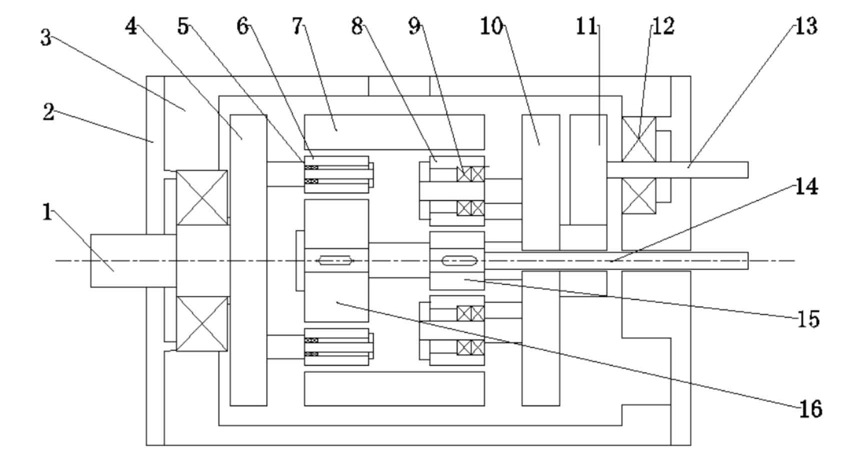
Firstly, the overall layout of the whole planetary gear transmission structure is carried out in CAD, and the plane layout of the whole structure is shown in Figure 1:
The parametric simulation model is established in solidworks, and the simulation part drawing obtained from parametric 3D modeling is shown in Figure 3.2. Where: 2 (a) is the inner gear ring of the transmission system, 2 (b) is the sun gear at the input end, 2 (c) is the sun gear at the output end, 2 (d) is the planetary gear at the input end, 2 (e) is the planetary gear at the output end, 2 (d) is the planetary gear at the input end, 2 (h) is the planetary gear carrier at the output end, and 2 (i) is the planetary gear connecting shaft.