Spiral bevel gear is point contact conjugate transmission. Under light load, the gear pair forms an elliptical contact area near the contact point. In order to obtain the direction of the long axis of the contact ellipse, it is necessary to know the curvature in any direction at the contact point, so the gear meshing principle formula should be used.
Given the parameters T, a and R0 of the cutter head during machining, we can know the curvature of the point on the cutter head, kn1, kn2 and short-range torsion along the circumferential direction and tooth height direction τ g. Using the formula in the gear meshing principle, the induced curvature of the tool and workpiece at this point can be obtained, and the curvature and short-range torsion of this point along any direction on the tooth surface can be obtained from the induced curvature.
After the curvature and short-range torsion of the corresponding contact points of the large and small wheels are obtained, the included angles of the tooth height directions T1 and T2 when the large and small wheels are rotated and correctly contacted respectively are solved τ。 The curvature of the small wheel is transformed into the value on the gear tooth surface, and then the relative curvature of the large and small wheels is obtained, and then the relative curvature along any direction is obtained from the relative curvature. According to experiments, Gleason confirmed that when the distance between two surfaces △ δ ≤ 0.00635, the contact marks on the tooth surface can be checked with red lead powder. The size of the contact area when the two tooth surfaces are running is determined according to this principle. By △ δ= The formula of 1 / 2 • △ kn • (△ s) 2 is △ s in each direction of the contact point, in which the maximum value is the long axis of the gear contact ellipse and the minimum value is its short axis. The ellipses of a group of tooth surface contact points are obtained continuously, and their set is the contact area. The following figure is the calculated tooth surface contact area and motion curve.
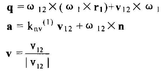
Formulas of induced curvature:


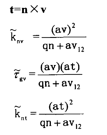
Curvature in tooth length direction:

Curvature in tooth height direction:

Short range torsion in tooth length direction:

Rotate the large and small wheels separately η 1, η 2 calculate the included angle between T1 and T2 after the rotation angle τ:
Because:

So:

The curvature and short-range torsion of the points on the pinion tooth surface are mapped to the gear tooth surface as follows:

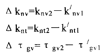
The relative curvature and relative short-range torsion are:

The relative curvature in any direction is obtained by Euler formula:

In the formula:
Knv2, knv1 – curvature in the long direction of large and small gear teeth;
Knt2, knt1 – curvature in height direction of large and small gear teeth;
τ gv2, τ GV1 – short range torsion of large and small gear teeth in the long direction;
△ s – is the half axis length of the contact ellipse in the kn direction.

