
The reliability of our production lines is paramount. As a key power transmission component, the stability of speed reducers directly impacts the operational continuity and efficiency of our entire system. Over years of operation, we have observed persistent challenges with a significant number of cycloidal drive units installed on medium to low-load equipment such as belt conveyors, screw conveyors, and bucket elevators. Common issues included frequent failures of eccentric bearings and cycloidal discs, recurring oil leakage leading to lubricant loss and environmental contamination, and complex maintenance procedures. To address these challenges, we initiated a systematic program to retrofit these cycloidal drive units with parallel shaft gear reducers (such as ZSY and ZQ types). This initiative leveraged our inventory of spare parts from decommissioned or upgraded equipment, focusing on enhancing reliability without procuring new units.
Comparative Analysis: Cycloidal Drive vs. Parallel Shaft Gear Reducer
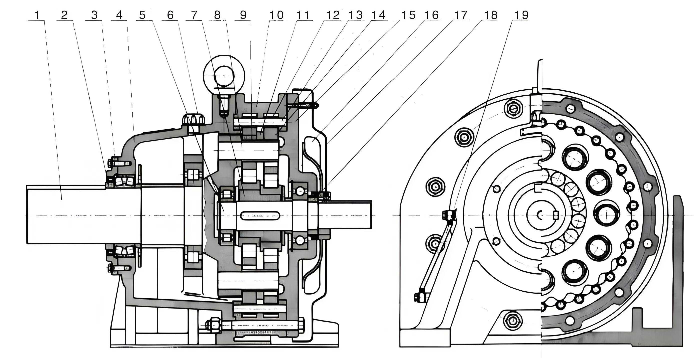
A thorough technical comparison is essential to understand the rationale behind the retrofit. The fundamental operational principles and construction of a cycloidal drive differ significantly from those of a standard gear reducer.
The cycloidal drive operates on a principle involving an eccentric input bearing that causes a set of cycloidal discs to undergo a compound epicyclic motion. This motion, transmitted through pins and rollers in the stationary ring gear, results in a high reduction ratio in a single stage. The kinematic relationship for speed reduction can be expressed as:
$$ i = \frac{N_p}{N_p – N_d} $$
where \( i \) is the reduction ratio, \( N_p \) is the number of pins in the ring gear, and \( N_d \) is the number of lobes on the cycloidal disc. This design yields high torque density.
In contrast, a parallel shaft helical gear reducer achieves its ratio through multiple meshing gear stages. The total ratio is the product of the ratios of each stage:
$$ i_{total} = i_1 \times i_2 \times i_3 \times … $$
where each stage ratio \( i_n = \frac{Z_{driven}}{Z_{driver}} \), with \( Z \) representing the number of teeth.
The following table summarizes the key comparative characteristics:
| Feature | Cycloidal Drive | Parallel Shaft Gear Reducer |
|---|---|---|
| Principle & Structure | Epicyclic (planetary) motion using eccentric bearings, cycloidal discs, pins, and ring gears. Compact, high power density. | Multi-stage meshing of parallel helical gears. Simple, robust structure. |
| Reduction Ratio | Very high single-stage ratios achievable (e.g., 6:1 to 119:1). | Lower ratio per stage. High total ratios require multiple stages, increasing size. |
| Efficiency | Generally high (90-95%) but can degrade with wear on pins/rollers. | Typically high (94-98% per stage), stable over time with proper lubrication. |
| Overload & Shock Load Capacity | Good due to multiple rolling contact points sharing load. | Excellent, especially with hardened gears. Handles high momentary peaks well. |
| Maintenance & Serviceability | Complex. Requires precise alignment of eccentric components. Specialized knowledge needed. Frequent bearing and seal issues. | Straightforward. Standard bearing and gear inspection/replacement. Easier shaft seal maintenance. |
| Lubrication & Sealing | Often uses grease, but oil-filled units prone to leakage at eccentric shaft seals, a common failure point. | Uses oil bath lubrication. Multiple, more reliable sealing options (lip seals, labyrinth seals) are standard. |
| Noise & Vibration | Can be noisier due to the oscillating motion of components. | Generally quieter and smoother running due to continuous helical gear contact. |
| Cost & Availability | Lower initial cost for basic models. Specialized parts can be costly and have longer lead times. | Moderate initial cost. Standardized gear and bearing components are widely available. |
While the cycloidal drive offers compactness and high ratio in a single stage, its weaknesses in maintenance complexity and seal reliability became critical in our high-availability environment. The gear reducer’s simplicity, robustness, and superior sealing made it a more suitable choice for long-term, reliable operation in many of our applications.
Retrofit Case Studies and Technical Evaluation
The decision to replace a cycloidal drive was never arbitrary. Each case involved a detailed technical assessment to ensure suitability, correct sizing, and optimal utilization of available resources.
Case 1: Cement System Long Belt Conveyor
The original equipment used an XWDY-7-7.5-29 cycloidal drive (7.5 kW, i=29). After changing the conveyed material, failure frequency increased dramatically, requiring bi-monthly changes of the standby unit, risking production stoppages.
Technical Analysis: The new material likely increased the consistent torque demand or introduced mild shock loads, accelerating wear in the cycloidal drive‘s precision components. We selected a DCY180 gear reducer from stock. Power verification was crucial. The required output torque \( T_{out} \) is given by:
$$ T_{out} = \frac{9550 \times P}{n_{in}} \times i \times \eta $$
Where \( P \) is motor power (7.5 kW), \( n_{in} \) is input speed (~1500 rpm), \( i \) is the required ratio (~29), and \( \eta \) is efficiency. The DCY180 was verified to handle this torque with an adequate service factor. The retrofit resolved both the reliability and leakage issues, with over two years of fault-free operation.
Case 2: Raw Material System Belt Conveyor
A 30 kW cycloidal drive suffered from chronic oil leakage on the motor shaft side. Seal replacements provided only temporary fixes for weeks, leading to significant oil loss (~15 kg/month).
Technical Analysis & Downsizing Opportunity: We analyzed the actual operational data. The motor current \( I_{actual} \) was consistently well below the motor’s rated current \( I_{rated} \). The actual power draw \( P_{actual} \) can be estimated by:
$$ P_{actual} \approx \sqrt{3} \times V \times I_{actual} \times \cos\phi $$
This calculation confirmed the drive was substantially oversized. We replaced it with a gear reducer matched to a 22 kW motor. The gear reducer’s service factor \( SF \) for this application was calculated to ensure reliability:
$$ SF = \frac{P_{Gear\ Reducer\ Rated}}{P_{Application\ Required}} > 1.5 $$
This approach not only solved the leakage problem inherent to the cycloidal drive design but also realized energy savings by right-sizing the drive system.
Comprehensive Benefit Analysis and Quantified Results
The cumulative impact of retrofitting fifteen cycloidal drive units has been substantial. The benefits extend beyond simple maintenance cost avoidance to include energy savings, reduced downtime, and environmental improvements.
The following table breaks down the annual savings per average retrofitted unit, based on our operational data:
| Cost Category | Cycloidal Drive (Annual) | Gear Reducer (Annual) | Annual Savings per Unit |
|---|---|---|---|
| Maintenance & Parts | $11,000 (1-3 major repairs, bearings, seals, discs) |
$2,000 (routine inspection, occasional seal) |
$9,000 |
| Lubricant Loss | $400 (15 kg/month loss) |
$50 (minimal seepage) |
$350 |
| Energy Consumption | Based on original motor (e.g., 30 kW) | Based on right-sized motor (e.g., 22 kW) | See calculation below |
| Downtime & Logistics | $2,000 (Production delay, crane rental for overhead units) |
$500 | $1,500 |
| Total Direct Savings | >$10,850 |
Energy Savings Calculation: For the case where power was downsized from 30 kW to 22 kW, with an 8 kW load reduction, operating 24/7 (8,760 hours/year) at an electricity cost of $0.053/kWh:
$$ Savings_{energy} = \Delta P \times Hours \times Cost = 8\ kW \times 8760\ h \times 0.053\ $/kWh $$
$$ Savings_{energy} \approx $3,714\ per\ year\ per\ applicable\ unit $$
When combining direct maintenance savings with energy savings from downsizing opportunities, the total annual saving per unit averaged approximately $13,000. For 15 units, this translates to nearly $195,000 in annual cost avoidance and savings. Furthermore, the increase in overall equipment effectiveness (OEE) due to reduced unplanned stoppages provides additional, harder-to-quantify value in production consistency and planning.
Conclusion and Operational Philosophy
The systematic replacement of problematic cycloidal drive units with robust parallel shaft gear reducers has proven to be a highly successful strategy. This practice was not a blanket condemnation of all cycloidal drive technology; high-quality units in suitable applications remain reliable. However, for the specific duty cycles and maintenance realities of our plant’s conveying and feeding equipment, the inherent weaknesses of the cycloidal drive—particularly in sealing and ease of repair—became unacceptable liabilities.
By leveraging existing resources, conducting thorough technical evaluations for each application, and capitalizing on opportunities to right-size drives, we achieved multiple objectives: a drastic reduction in maintenance workload and costs, elimination of chronic lubricant leaks, significant energy savings, and a marked improvement in equipment reliability and availability. This approach exemplifies a sustainable and pragmatic engineering philosophy focused on lifecycle cost and operational stability rather than merely initial purchase price, ensuring the long-term health and efficiency of our production infrastructure.