Abstract
This paper addresses the inaccuracy issue in modeling double-lead worm gears. By analyzing the working and manufacturing principles of double-lead worm gears, a modeling method is proposed, which involves generating accurate worm tooth profiles through spiral turning motion of the tool along the contact line with the worm, and subsequently creating the worm gear tooth profiles using the conjugate of the worm tooth profiles. This method is implemented in UG software and proven to be precise, simple, and effective for modeling various tooth profile curves and leads of common cylindrical worms. The results provide a foundation for kinematic analysis, finite element analysis, and CNC machining of worm gear sets.

1. Working and Manufacturing Principles of Double-Lead Worm Gear
1.1 Working Principle of Double-Lead Worm Gear
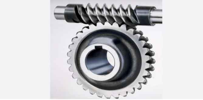
Double-lead worms can be classified into types such as involute, extended involute, and prolonged involute based on the tooth shape in the end face. The working principle of a double-lead worm gear is similar to that of a standard cylindrical worm gear. In an axial cross-section of the worm, the worm resembles a rack, and the worm gear resembles a gear. The double-lead worm features different leads on its left and right tooth surfaces, with equal leads on the same side, resulting in a gradual increase in axial tooth thickness from one end to the other. The axial tooth pitch, leads, module, and spiral lead angle differ between the left and right tooth surfaces.
Table 1. Parameters of Double-Lead Worm
| Parameter | Description | Symbol |
|---|---|---|
| Nominal axial tooth pitch | Average tooth pitch | t0 |
| Axial tooth pitch on left side | Left-side tooth pitch | tz = t0 + Δt |
| Axial tooth pitch on right side | Right-side tooth pitch | ty = t0 – Δt |
| Difference in tooth pitch | Δt |
1.2 Manufacturing Principle of Double-Lead Worm Gear
Worms are typically manufactured using straight-edged lathe tools. The type of worm produced depends on the position of the tool’s cutting edge relative to the worm.
- (a) Achimedean Worm (ZA): The blade lies in the axial plane of the worm, and the tooth surface is an Achimedean spiral.
- (b) Extended Involute Worm (ZN): The blade is inclined to the helix angle of the worm’s reference cylinder, and the tooth surface is a normal straight-profile spiral.
- (c) Involute Worm (ZI): The blade is placed in the tangent plane of the base cylinder, and the tooth surface is an involute spiral.
Table 2. Types of Worms and Their Manufacturing Characteristics
| Type | Blade Position | Tooth Surface |
|---|---|---|
| Achimedean Worm (ZA) | Axial plane | Achimedean spiral |
| Extended Involute Worm (ZN) | Normal section | Normal straight-profile spiral |
| Involute Worm (ZI) | Tangent plane of base cylinder | Involute spiral |
2. Tooth Profile Analysis and Calculation of Double-Lead Worm Gear
2.1 Parameter Equations of Tooth Spiral Surface Using Vector Algebra
To describe the spiral motion of a vector, we use the following transformations:
- Rotation about the k-axis:
x′y′z′=cosϕsinϕ0−sinϕcosϕ0001xyz
- Rotation about the j-axis or i-axis (similar transformations apply).
- Combined rotation about the k-axis and translation along the k-axis:
x′y′z′=cosϕsinϕ0−sinϕcosϕ0001xyz+00pϕ
Where p is the pitch (positive for right-handed helix, negative for left-handed helix), and ϕ is the angle of rotation. The trajectory of the vector r(x,y,z) is a spiral line.
Conclusion
The proposed modeling method for double-lead worm gears based on UG software ensures precision and simplicity, making it suitable for various tooth profile curves and leads. This method provides a solid foundation for further analysis and manufacturing of worm gear sets.
