1. Tooth profile involute analysis
The key to accurate modeling of gears is to construct involutes of gear teeth. The polar coordinate equation of involutes is:
Where: rk is the radius of the dividing circle; RB is the radius of the base circle; α K is the involute pressure angle; θ K is an involute function.
The shape of the involute depends on the size of the base circle, and the equation of the radius of the base circle is:
Where: m is the gear module; Z is the number of gear teeth; α Is the gear pressure angle, generally taken as 20 °.
The larger the base circle is, the straighter the involute is. When the radius of the base circle is infinite, the involute becomes a straight line.
2. Construct involute
Taking the standard involute gear with module m of 3mm and tooth number Z of 14 as an example, the involute is constructed.
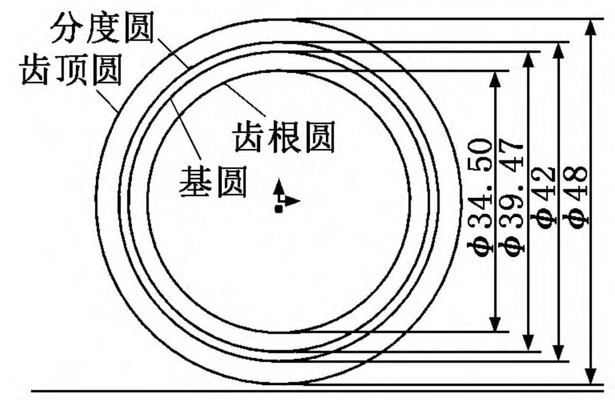
(1) Enter the sketch drawing interface and draw the graduation circle, base circle, addendum circle and root circle according to the dimensions obtained by the formula, as shown in Figure 1.
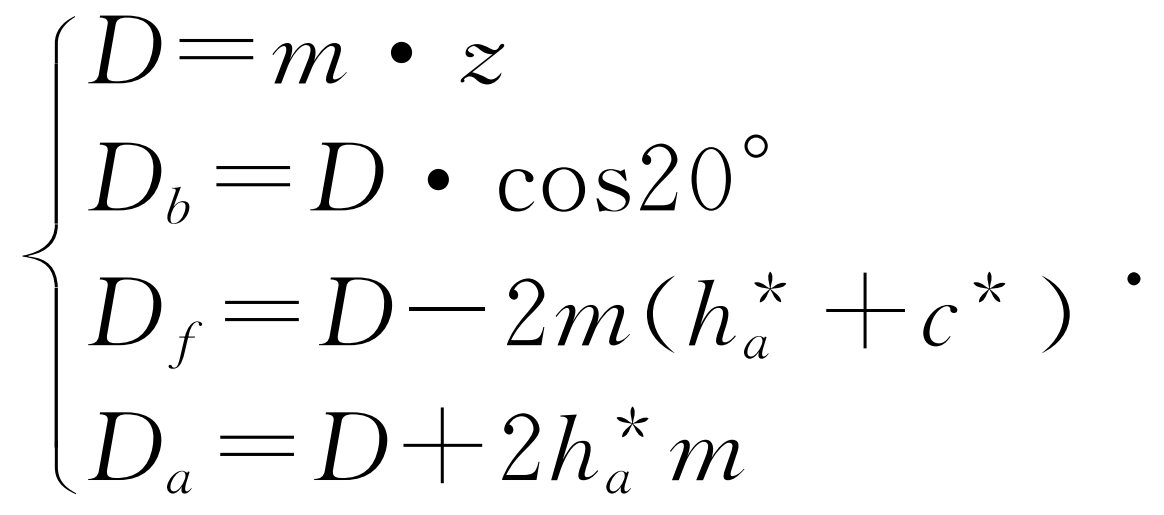
Where: D is the diameter of the dividing circle; DB is the diameter of the base circle; DF is the diameter of the root circle; Da is the diameter of the addendum circle; C * is the addendum clearance coefficient, taking c * = 0 25; H * a is the addendum height coefficient, taking h * a = 1.
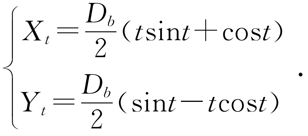
(2) In “equation driven curve”, select the “parametric” equation, input XT and YT respectively according to the formula, and use the parametric variable t to form the curve length to obtain the gear involute sketch as shown in Figure 1.
3. Tooth configuration and modeling
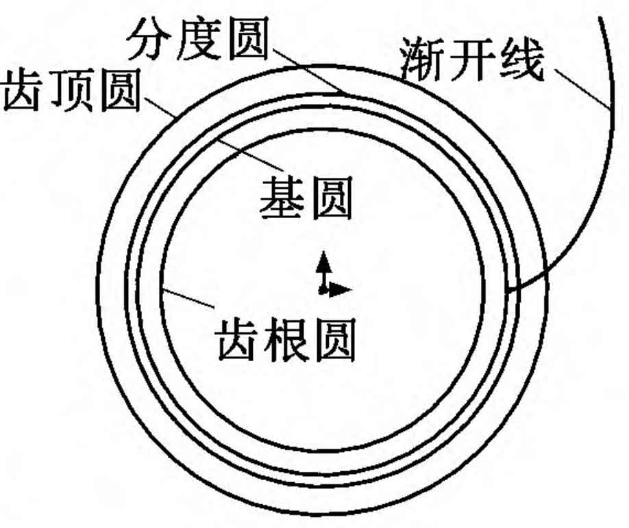
Draw a center line for mirroring the involute, use the “mirror” command on the gear involute in Figure 2, make two involutes form two side lines of a tooth, define the tooth thickness s on the indexing circle according to the formula, define the coincidence constraint between the tooth thickness line and the involutes on both sides, then trim the root circle and the indexing circle, draw the root fillet, and make the drawn root fillet tangent to the base circle and the root circle. See the formula for the radius r of the root fillet, So far, the drawing of a gear tooth is completed. After that, the sketch is extruded, arrayed, keyway and other commands, and finally the three-dimensional shape of the gear as shown in Figure 3 can be obtained.