
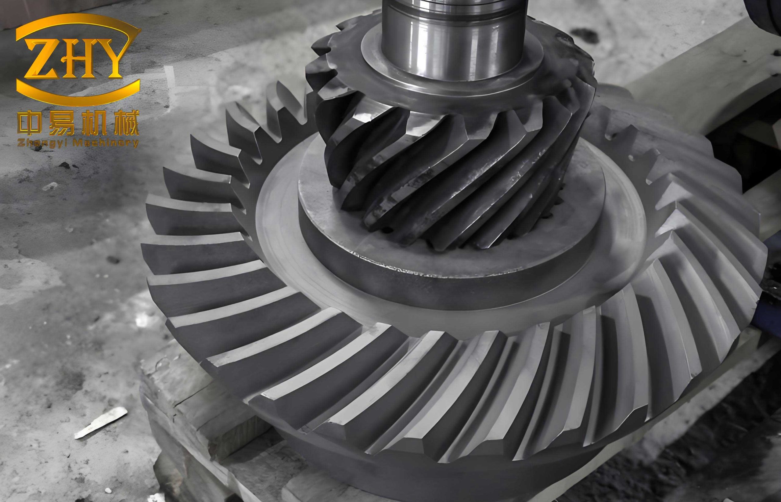
Our work focuses on the development of a novel manufacturing process for automotive final drive helical bevel gear pairs. Traditionally, these critical components require high-quality alloy steels and complex machining operations, particularly the gear cutting process which depends on several expensive imported Gleason machines and a complete set of supporting tools and equipment. This creates a significant bottleneck in supply, especially for medium and small-scale factories and repair shops, often hampering vehicle maintenance and operation. To address this challenge and in line with the principles of self-reliance and utilizing both advanced and indigenous methods, we initiated experiments to produce helical bevel gears using ductile iron (specifically, rare-earth alloyed ductile iron) and the precision investment casting process. The finished products, a drive pinion and a driven ring gear, are characterized by a high tooth count, small module, and large spiral angle, making them among the more difficult types to cast. Preliminary results have been promising.
To stabilize and improve the quality of these precision-cast helical bevel gears, systematic studies were conducted over the past two years. We measured the isothermal transformation curves, critical points, and martensite start (Ms) point for the rare-earth alloyed ductile iron, leading to the determination of an optimal heat treatment process that enhances the overall material properties. Experiments with pattern gears of varying mesh geometry and the application of an electro-spark running-in process have significantly improved both the appearance and internal quality of the gears, increasing tooth surface finish and meshing accuracy. Most importantly, rigorous road tests under severe conditions, including tests on two vehicles and extended use on six others, have subjected the ductile iron helical bevel gears to practical operational challenges. The results confirm that substituting rare-earth alloyed ductile iron and precision casting for the traditional alloy steel and gear milling process for automotive drive pinions and ring gears is successful. This provides a new pathway for medium and small-scale factories to produce such helical bevel gears. However, our findings are still preliminary. Guided by the principle of conscientiously summarizing experience to affirm achievements and identify problems for future improvement, we present the following summary.
I. Performance Testing of Ductile Iron Gears
A. Material Property Comparison
Conventional steel gears employ a surface carburizing, quenching, and low-temperature tempering process to achieve a favorable combination of strength, hardness, and toughness. To evaluate whether austempered ductile iron (ADI) could attain comparable properties, comparative tests were performed on specimens from both materials. Key parameters for the drive pinion are: Spiral Direction: Left; Spiral Angle: $$35^\circ$$; Mean Pressure Angle: $$21^\circ 30’$$; Module: 5.5 mm; Number of Teeth: 9; Whole Depth: 10.73 mm; Addendum: 4.98 mm. For the driven gear: Spiral Direction: Right; Number of Teeth: 41; Other parameters are correspondingly matched.
The steel specimens were taken from the splined shaft of a drive pinion (approx. 30 mm diameter). The ductile iron specimens were taken from 20 mm thick wedge-shaped test blocks. Steel specimens underwent standard carburizing, quenching, and tempering alongside production gears. The ductile iron heat treatment involved heating at $$880^\circ C$$ for 80 minutes, followed by isothermal treatment at $$280^\circ C$$ for 90 minutes.
| Property | Steel (20CrMnTi) | Ductile Iron (Rare-Earth) | Notes |
|---|---|---|---|
| Tensile Strength (kg/mm²) | 118.5 | 133.8 | |
| Surface Hardness (HRC) | 59.1 | 49.9 | |
| Impact Value (kg·m/cm²) | 7.25 | 10.7 | Un-notched specimen, 10x10x55 mm |
| Bending Fatigue Limit (kg/mm²) | 54.5 | 35.2 | Un-notched specimen, d=7.5 mm |
The results indicate that the rare-earth alloyed ductile iron exhibits higher tensile strength and impact value than the steel, but lower bending fatigue strength and surface hardness.
B. Static Torsional Strength Comparison
To compare the structural strength of the gear teeth themselves, static torsion tests were conducted on complete gear assemblies. The test setup involved mounting the gear pair in a support housing, locking the driven gear, and applying torque to the drive pinion via a lever arm. Torque (T) and angular deformation were recorded. The torque was calculated as: $$ T = F \times L $$ where F is the applied force and L is the lever arm length (1 meter). Deformation was measured as the vertical displacement of a point on the lever arm.
The results showed that the weak point was not the gear teeth but the splined shaft of the drive pinion. Therefore, the torque at which the spline shaft began plastic deformation was used for comparison. The results are summarized below:
| Gear Pair No. | Material | Plastic Deformation Torque (kg·m) | Final Torque (kg·m) | Microstructure Notes |
|---|---|---|---|---|
| 1 | Steel | 154 | 220 | – |
| 2 | Steel | 149 | 220 | – |
| 3 | Ductile Iron | 173 | 237 | Higher carbides & phosphide eutectic (~5%) |
| 4 | Ductile Iron | 170 | 230 | Small amount of ferrite (~3%) |
| 5 | Ductile Iron | 170 | 235 | Fine bainitic structure |
The static torsional strength of the rare-earth ductile iron (approx. 170 kg·m) was slightly higher than that of the steel (approx. 150 kg·m), representing about 6 times the maximum working torque (27 kg·m). Variations in the ductile iron microstructure (e.g., small amounts of ferrite, phosphide eutectic content, bainite morphology) did not significantly affect the static torsional strength of the helical bevel gear.
II. Road Testing
While material tests showed ductile iron had higher static strength but lower dynamic (fatigue) performance and hardness, actual service conditions provide the most reliable validation. Therefore, intensified road tests were conducted, including mountain roads with full trailer loads, sandy beaches, and tank testing grounds. The test program is summarized below:
| Vehicle No. | Test Phases | Load Condition | Mileage per Phase (km) | Total Test Mileage (km) | Notes |
|---|---|---|---|---|---|
| A | Mountain Roads, Beach | Full Load, Overload | 15,000 | 34,000 | New test gears installed in rear axle after initial run-in. |
| B | Gravel Roads, Beach | Overload, Full Load | 5,000 | 15,000 | Test gears installed in rear axle. |
Post-test inspection focused on gear tooth wear and surface condition:
| Vehicle | Mileage (km) | Tooth Surface Condition | Wear Measurement (mm) | Backlash Change (mm) |
|---|---|---|---|---|
| A | 2,500 | Small pits appear on drive pinion. | 0.05-0.10 | 0.10 → 0.20 |
| 5,000 | Pits slightly enlarged/deepened (~0.2mm). | 0.10-0.15 | – | |
| 15,000 | Pits remain, surfaces brighten. | ~0.20 | – | |
| 34,000 | Surfaces smooth, pits nearly disappeared. | No measurable wear | Adjusted to 0.10-0.15 | |
| B | 15,000 | Surfaces smooth, minor pitting on 2-3 teeth. | No measurable wear | – |
The intensified road tests yielded key findings: First, no tooth breakage occurred after a total of 34,000 km under severe conditions, demonstrating that the ductile iron helical bevel gear possesses sufficient bending fatigue strength and impact load capacity. Second, initial wear of 0.20-0.25 mm occurred in the first 5,000 km, after which no further measurable wear was detected, even following beach and tank track testing. This indicates good wear resistance despite lower hardness. The initial wear is attributed to surface decarburization from heat treatment (approx. 0.1-0.2 mm deep) and imperfect initial contact pattern from manual correction of the as-cast gears.
Third, small pits appeared on the tooth flanks around 2,500 km, primarily on the drive pinion. Unlike typical steel gear pitting, these pits were shallow, had smooth contours, and their progression was extremely slow. With continued use, the pits often became smoother and lighter, sometimes disappearing entirely. This behavior contrasts sharply with progressive spalling in steel gears. We theorize that the lower hardness (exacerbated by decarburization) and the presence of graphite nodules lead to early surface pitting under contact stress. However, the graphite nodules also act as crack arresters, preventing propagation. As the surface work-hardens and the contact pattern improves through wear, the pitting damage stabilizes or even diminishes, allowing for continued reliable service of the helical bevel gear.
III. Production Process for Precision-Cast Ductile Iron Gears
A. Casting Process
The gears are produced using a resin-coated shell molding process. The molding sand consists of a facing sand (resin-coated silica flour, ~15-20 mm thick) and a backing sand (ordinary molding sand). The resin is a phenol-formaldehyde type. The silica flour has a specified grain size distribution. The resin binder addition is 4-5%. Mixing time is 8-10 minutes. Mold drying is conducted at 180-200°C for 2-3 hours.
A critical development was the design of the pattern gear. Initially, using a standard hardened steel gear as the pattern resulted in a significant shift of the contact pattern towards the toe and top of the tooth on the cast gear, reducing contact area. This required extensive manual correction or electro-spark running-in. To solve this, experiments were conducted with pattern gears made with a 2% linear shrinkage allowance and modified spiral and pressure angles. The results are summarized below:
| Pattern Gear Type | Contact Pattern on Cast Gear | Conclusion |
|---|---|---|
| Standard Steel Gear (No allowance) | Shifted severely to toe/top. Area ~20-30%. | Unsatisfactory, requires extensive post-casting correction. |
| With 2% linear allowance only | Improved, but still not optimal. | Better, but may still need running-in. |
| With 2% allowance & modified spiral/pressure angles | Contact pattern meets requirements (~60-70%). | Optimal for direct use or minimal running-in. |
Consequently, the final production uses a corrected pattern gear with a 2% shrinkage allowance for the drive pinion, and a pattern with increased outer diameter for the driven gear. The gear teeth are cast to net shape, while other surfaces have a 2-3 mm machining allowance. Molds are assembled using locating pins for dimensional consistency.
The iron is melted in a basic arc furnace. The target base iron composition is: C: 3.6-3.9%; Si: 1.8-2.2%; Mn: <0.5%; P: <0.1%; S: <0.03%. Treatment is performed in a ladle. A 1# rare-earth magnesium alloy is used as the nodularizer, added at 1.6-1.8%. Post-inoculation is done with 75% FeSi at 0.6-0.8%. The treatment temperature is ~1420°C, with a pouring temperature of ~1320°C. The as-cast microstructure shows spheroidal graphite with minimal carbides and phosphide eutectic.
B. Machining
Machining is required for non-tooth features. Accurate location is paramount for ensuring proper meshing of the as-cast tooth flanks of the helical bevel gear.
Drive Pinion: The key step is drilling center holes. The gear is first chucked by the shaft body, and the conical back face is used for alignment (runout <0.05 mm). The center hole is drilled in one end. The gear is then transferred to a fixture that locates on the cast teeth, and the shaft is machined to final length and the second center hole is drilled. All subsequent turning is done between these centers.
$$ \text{Runout Tolerance} \leq 0.05 \text{ mm} $$
Driven Gear: The gear is initially held by chucking the riser. The outer diameter, top face, and back face are machined as preliminary datums. The gear is then re-chucked using these machined surfaces for final alignment before finishing the bore, back face, and cutting off the riser.
C. Heat Treatment
All gears undergo austempering to achieve a bainitic microstructure (ADI) for optimal combination of strength and toughness. Systematic studies, including measurement of the Isothermal Transformation (TTT) diagram, were conducted to establish the process. The critical temperatures Ac1 and Ac3 were found to be ~735°C and ~825°C, respectively, for our alloy composition. The Ms point is ~250°C. The final heat treatment cycle is: Austenitize at $$880 \pm 10^\circ C$$ for 80 minutes, then quench rapidly into a salt bath at $$280 \pm 10^\circ C$$ and hold for 90 minutes, followed by air cooling.
Heating is done in a salt bath furnace, with the salt deoxidized to minimize surface decarburization. Gears are suspended vertically. After austempering, the hardness at the tooth tip and pinion shaft is approximately HRC 50. Dimensional changes occur: the driven gear outer diameter increases by ~0.20 mm on average; the bore becomes slightly oval. The pinion shaft diameter increases by 0.10-0.15 mm. Despite these changes, all heat-treated gears passed the standard inspection criteria used for steel gears. The microstructure after treatment consists of bainite with dispersed graphite nodules.
D. Electro-Spark Running-In
This process serves as a final precision finishing for the tooth flanks of the helical bevel gear. It is particularly useful for correcting minor deviations in the as-cast tooth geometry and improving surface finish. The setup involves mounting the gear pair in an insulated housing. A pulsed power supply is connected to the gears via brushes. The gears are run at a moderate speed (800-1200 rpm) in a bath of heavy gear oil (the dielectric medium). Material is preferentially removed from high points until full contact is achieved.
The electrical parameters are crucial. A two-stage approach is used: initial “roughing” with higher voltage/pulse energy to quickly establish contact area, followed by “finishing” with lower voltage/pulse energy to improve surface finish. Typical parameters are:
| Stage | Frequency (Hz) | Voltage (V) | Speed (rpm) | Purpose |
|---|---|---|---|---|
| Roughing | 10,000 – 20,000 | 80 – 100 | 800 – 1200 | Rapidly expand contact area. |
| Finishing | 40,000 – 60,000 | 50 – 70 | 800 – 1200 | Improve surface finish. |
A comparison of production methods highlights the role of this process:
| Method | Advantages | Disadvantages | Best Application |
|---|---|---|---|
| Cast + Manual Grinding | No special pattern or equipment needed. | Very low efficiency, inconsistent contact pattern. | Single-piece repair. |
| Std. Pattern + E-Spark Run-in | No special pattern gear needed. | Requires E-spark equipment, significant running-in alters tooth profile. | Small batches with existing E-spark capacity. |
| 2% Allowance Pattern + E-Spark Run-in | Pattern easier to make, good contact pattern. | Still requires E-spark equipment. | Small batch production. |
| Corrected Pattern (2% + angles) + Minimal E-Spark | Best contact pattern and accuracy, minimal running-in needed. | Requires dedicated, corrected pattern gears and E-spark equipment. | Batch production requiring high quality. |
IV. Economic Impact
The successful implementation of precision-cast ductile iron helical bevel gears presents significant economic advantages. Primarily, it eliminates the dependency on scarce alloy steel and expensive, specialized gear-cutting machinery. Quantitatively, each gear pair saves approximately 6 kg of low-alloy steel. For an annual production of 10,000 pairs, this translates to a saving of 60 tons of steel. In terms of material cost, the steel for a traditional gear pair costs about 12 RMB, while the ductile iron material costs only 3 RMB, a 75% reduction. This yields a material cost saving of 9 RMB per pair, amounting to 90,000 RMB annually for 10,000 pairs.
While our experimental phase involved manual setup and lacked dedicated tooling, precluding an exact machining cost comparison, the core economic benefit is undeniable: the elimination of the most complex and capital-intensive machining step—gear tooth generation. This drastically lowers the barrier to entry for production, making it feasible for smaller enterprises to manufacture these critical helical bevel gear components.
V. Basic Requirements for Ductile Iron Gear Castings
Based on our experimental findings, the following basic specifications are proposed for the ductile iron gear castings. A formal technical standard will require further batch production experience.
1. Chemical Composition (%)
Final (Cast): C: 3.6-3.9; Si: 2.3-2.7; Mn: <0.5; P: <0.1; S: <0.03; Mgres: >0.03; REres: >0.02.
2. As-Cast Microstructure
Graphite Form: >80% spheroidal (nodular).
Graphite Size: Mostly 5-6 (ASTM). Some 4 allowed.
Matrix: Predominantly pearlitic/ferritic, with carbides and phosphide eutectic <3%.
3. Casting Surface Quality
Tooth profiles must be sharp and clear. No cold shuts or misruns are permitted on the teeth. After shot blasting, the tooth flanks must be free of sand inclusions, slag holes, or blowholes. Any adhering sand grains or hard spots must be removed by grinding or stoning.
In conclusion, the development of rare-earth alloyed ductile iron precision-cast helical bevel gears has proven technically viable and economically advantageous. The gears meet the fundamental performance requirements for automotive applications, as validated by material tests and extensive road testing. The process provides a practical alternative for manufacturers lacking access to specialty steels and dedicated gear-cutting resources. Future work will focus on systematic gear fatigue bench testing, larger-scale durability trials, further refinement of casting quality, and enhancement of dynamic performance properties.