
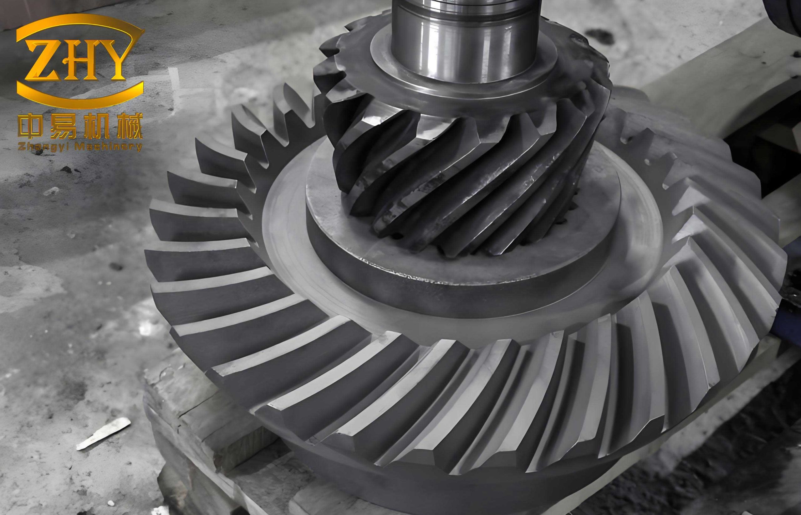
The manufacturing of high-strength, durable power transmission components is a cornerstone of modern mechanical engineering. Among these, helical bevel gears are critical for applications requiring efficient torque transfer between non-parallel, intersecting shafts, such as in automotive differentials, heavy machinery, and aerospace systems. The performance, longevity, and noise characteristics of these helical bevel gears are intrinsically linked to the quality of their forged blank. A superior forging process ensures optimal grain flow, enhanced mechanical properties, and near-net-shape geometry, minimizing wasteful machining. This discourse delves into a significant advancement in the precision forging technology for helical bevel gear blanks, moving from a problematic conventional method to an innovative, floating-die design that eliminates wasteful flash and enhances material utilization.
Traditionally, the production of blanks for helical bevel gears often involved a multi-step process: upsetting, piercing, ring rolling to create a preform, and finally, a finish forging operation. The conventional finish forging die, typically a closed-die system where an upper punch descends into a lower die cavity, presented a persistent and costly flaw. To facilitate ejection, the central punch was designed with a draft angle (5°–7°). This design, however, resulted in the formation of longitudinal flash—a thin, vertical fin of metal—along the internal bore of the forged blank during the final metal flow. The consequences of this flaw were multifaceted:
- Increased Material Waste: The flash represented excess material that had to be machined away.
- Machining Difficulty: The hard, irregular flash often caused tool breakage (“tool chipping”) during subsequent lathe operations, disrupting production flow.
- Labor-Intensive Secondary Operation: Since this vertical flash could not be removed by standard trimming dies, manual hammering was required to knock it down—a process that was inconsistent, laborious, and added cost.
This inefficiency highlighted the need for a true precision forging approach for helical bevel gear blanks, one that could produce a flash-free part directly from the die.
Fundamentals of Precision Closed-Die Forging for Ring-Shaped Components
The core challenge in forging a ring-shaped component like a helical bevel gear blank is achieving complete cavity filling without generating flash. Flash forms when excess material escapes through a gap between die components. In a standard closed-die forging, the vertical movement of the upper die against the stationary lower die creates a parting line where flash is inevitable unless the billet volume is precisely controlled—a near-imperative in high-volume production.
The innovative solution lies in creating a fully enclosed, or trapped, annular cavity. This is achieved by allowing multiple die components to move relative to each other during the forging stroke. The principle can be modeled by considering the volume constancy of the plastic deformation and the kinematic relationships of the die movements.
Let \( V_0 \) be the precise volume of the preform ring. The final forged part volume \( V_f \) must equal \( V_0 \). The die cavity volume \( V_{cavity} \) is a function of the positions of the moving die elements. For a system with a floating core and a floating outer die segment, the cavity height \( h_{cavity} \) decreases during forging. The condition for flash-free forging is:
$$ V_0 = V_{cavity}(s_{punch}, s_{core}, s_{outer}) $$
where \( s_{punch} \), \( s_{core} \), and \( s_{outer} \) are the displacements of the main punch, floating core, and floating outer die, respectively, from their initial positions. Their movements are coupled through the geometry of the preform and the applied force. The key is that the final, fully closed shape of the cavity is achieved before the press stroke ends, physically preventing any material escape paths.
The Novel Floating-Die System: Architecture and Mechanics
The advanced die design to eliminate flash in helical bevel gear blanks employs a sophisticated system of floating components. The primary structural innovation is the decoupling of the forming cavity’s closure from the single downward motion of the press ram. The system can be broken down into key functional assemblies, as detailed in the table below.
| Component Group | Key Parts | Function & Mechanism |
|---|---|---|
| Upper Forming Assembly | Upper Die Insert, Floating Core, Spring Set | Forms the internal bore and top face. The core is pushed downward by springs initially and floats upward during forging, guided within the upper die. |
| Lower Forming & Ejection Assembly | Lower Die Insert, Ring Anvil, Combined Ejector (Insert Block + Spacer + Connector), Lower Pre-stress Ring | Forms the outer rim and bottom face. The entire lower insert assembly is supported by springs, allowing it to float downward. The combined ejector later pushes the finished part out. |
| Floating Mechanism & Guidance | Strong Compression Springs, Limit Bolts, Fixed Plate | Provides the resisting force for the floating movements, controls the range of float, and ensures precise alignment. The fixed plate houses the springs and serves as the datum for the lower assembly. |
| Prestressed Container System | Upper & Lower Pre-stress Rings, Split Die Inserts | Subjects the critical die inserts (upper and lower) to compressive hoop stresses, drastically increasing their fatigue life and allowing the use of higher-strength, potentially more brittle tool steels. |
| Alignment & Locking System | Matting Locking Lugs (Sunken Joint) on Pre-stress Rings | Ensures perfect lateral alignment between upper and lower dies before the forming surfaces contact, eliminating mismatch and reducing lateral forces on the guide pillars. |
The operational sequence is a symphony of coordinated movements:
- Pre-placement: The ring-shaped preform is placed over the combined ejector in the lower die. The floating core is in its lowest position, and the lower die assembly is in its highest position, held by springs.
- Die Closing & Cavity Formation: As the press ram descends, the locking lugs engage, aligning the dies. The upper die insert contacts the preform, and the floating core meets the ejector block. Continued ram movement compresses the preform. The reaction force pushes the floating core upward (compressing its springs) and pushes the entire lower die assembly downward (compressing its springs). A completely enclosed, flash-tight annular cavity forms around the deforming metal.
- Full Deformation: The press completes its stroke, the metal fully fills the intricate cavities defining the gear blank’s web and rim profiles, and the press energy is absorbed by the deformation and elastic deflection of the tooling.
- Ejection: On the ram’s return stroke, the spring forces return the floating components. Due to draft angles on the upper die insert and core, the part remains on the lower die insert. The press’s knockout system then activates the ejector, cleanly lifting the finished, flash-free helical bevel gear blank from the die.
Material Flow, Force Analysis, and Process Advantages
The material flow in this floating-die system is radically different from conventional forging. The metal is radially constrained from both the ID and OD simultaneously as the cavity height reduces. This promotes a more homogeneous strain distribution and superior grain flow alignment with the part’s contours. The forging force \( F \) can be conceptually broken down into components required for different actions:
$$ F \approx F_{deform} + F_{friction} + F_{spring} $$
Where \( F_{deform} \) is the ideal plastic deformation force, calculable using slab method or upper-bound theorem for ring compression; \( F_{friction} \) is the force to overcome friction at all die-workpiece interfaces; and \( F_{spring} \) is the additional force needed to compress the die springs. Crucially, \( F_{deform} \) is lower than in an open-die flash-forming process for the same final part because the projected area is the actual part area, not a larger area including flash land. This allows the use of a smaller capacity press (e.g., a 10,000 kN screw press) for the same part, or the forging of a larger helical bevel gear blank on an existing press.
The advantages of this new system for producing helical bevel gear blanks are quantifiable and significant:
| Parameter | Conventional Flash-Forming Die | Novel Floating Flash-Free Die | Improvement |
|---|---|---|---|
| Billet Weight | 9.3 kg | 8.79 kg | Reduction of 5.5% |
| Material Utilization | ~85-90% (with flash) | ~98-100% (flashless) | Increase of 8-13 percentage points |
| Secondary Operation | Manual flash removal required | No manual flash removal | 100% labor saving in this step |
| Machining Allowance | Larger, inconsistent due to flash | Minimal and consistent | Reduced machining time & cost |
| Part Quality | Risk of machining damage from flash | No internal defects from flash | Improved reliability and yield |
Tooling Design Nuances, Materials, and Life Considerations
The success of this precision forging process for helical bevel gears hinges on meticulous tooling design. The pre-stress container assembly is critical. The interference fits generate beneficial compressive stresses. For a two-layer container, the required interference \( \delta \) at the interface radius \( r \) can be estimated from Lamé’s equations for thick-walled cylinders. The optimal interference ensures the inner die insert is under a uniform compressive stress during the forging load’s peak.
Draft angles are strategically applied: a \( 15^\circ \) angle on the ejector block, a \( 12^\circ \) angle on the upper die insert, and a \( 5^\circ \) angle on the floating core. The lower die insert has zero draft. This staged release during ejection ensures the part reliably remains on the lower insert. The choice of spring constants for the floating mechanisms is a balance: they must be strong enough to position components accurately and resist initial buckling of the preform, yet not so strong as to significantly increase the total forging force.
Tool material selection is paramount for die life, especially for high-volume production of helical bevel gears. Key components like the die inserts and floating core undergo severe thermal cycling and mechanical fatigue. Common choices include hot-work tool steels like H13 (AISI), which offers a good balance of toughness, hot hardness, and thermal fatigue resistance. For even longer life, premium grades with improved cleanliness and micro-alloying or nickel-based superalloys might be used for critical wear surfaces, often applied as inserts or coatings.
$$ \sigma_{\theta, \text{inner}} = -p_c \quad \text{and} \quad \sigma_{\theta, \text{outer}} = p_c \frac{2r^2}{r_o^2 – r^2} $$
Where \( p_c \) is the contact pressure at the interference fit interface, \( r \) is the interface radius, and \( r_o \) is the outer radius of the container. The design goal is to keep \( \sigma_{\theta, \text{inner}} \) compressive under the maximum internal forging pressure \( p_i \).
Broader Applications and Future Outlook in Gear Forging
While demonstrated for an automotive rear axle helical bevel gear, the principles of this floating-die, flash-free forging technology are directly transferable to a wide array of complex, annular forgings. These include other types of differential gears, synchronizer hubs, heavy-duty bearing races, flanged coupling bodies, and ring components for the aerospace sector. The process is particularly advantageous for materials that are expensive, difficult to machine, or where superior forged properties are essential, such as high-alloy steels, titanium, and nickel-based alloys used in advanced helical bevel gears for aerospace transmissions.
The future evolution of this technology is closely tied to advancements in simulation and smart manufacturing. Finite Element Method (FEM) simulation software is now indispensable for optimizing preform design and predicting material flow, forging loads, and die stress to prevent premature failure. The next step involves integrating real-time process control, using sensors to monitor parameters like die displacement, temperature, and pressure. This data can be fed into a closed-loop system to adjust press parameters for each billet, compensating for material variability and die wear, ensuring consistently perfect flash-free forgings for every critical helical bevel gear.
Furthermore, the drive for sustainability and resource efficiency makes flashless forging increasingly compelling. The direct 5.5% savings in raw material for a single part, when scaled to global production volumes of helical bevel gears, translates into massive reductions in energy consumption for both steel production and scrap recycling. It represents a clear step towards greener manufacturing practices within the metallforming industry.
In conclusion, the transition from a traditional flash-forming die to an intelligent floating-die system for forging helical bevel gear blanks is more than an incremental improvement; it is a paradigm shift towards true precision. It eliminates wasteful secondary operations, enhances material utilization, improves part quality and consistency, and reduces the total cost of ownership. As the demands on gear performance and manufacturing efficiency continue to rise, such innovative forging technologies will remain vital for producing the high-integrity components that power our machines and vehicles.