1. Introduction
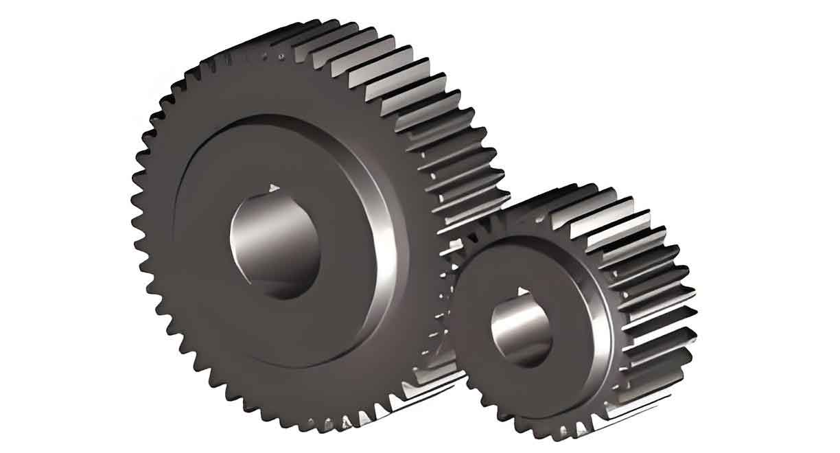
Spur gear, widely used in automotive and industrial machinery, demand high precision and durability. Traditional closed-die forging processes, while efficient, often face challenges such as excessive mold loads and reduced tool life. To address these issues, this study explores advanced forging techniques—floating die and hole split method—for spur gear production. Leveraging DEFORM-3D simulations, we evaluate their effectiveness in reducing mold stress and enhancing process sustainability.

2. Materials and Methods
2.1 Material Properties
The spur gear material, 20CrMnMo steel, was selected for its high strength and wear resistance. Key mechanical properties are summarized in Table 1.
Table 1: Mechanical Properties of 20CrMnMo Steel
| Parameter | Value |
|---|---|
| Tensile Strength | 1250 MPa |
| Yield Strength | 958 MPa |
| Elongation | ≥10% |
| Reduction of Area | ≥45% |
| Impact Energy | ≥55 J |
| Hardness (HB) | ≤217 |
| Poisson’s Ratio | 0.27 |
| Elastic Modulus | 207 GPa |
2.2 Process Design
Three forging strategies were investigated:
- Original Closed-Die Forging: Fixed die setup with high friction resistance.
- Floating Die: A movable die structure converts friction into aiding force.
- Hole Split Method: A central hole in the billet diverts material flow to reduce pressure.
Key Equations for Stress Analysis:
σeff=32S:Sσeff=23S:S
where σeffσeff is the von Mises stress and SS is the deviatoric stress tensor.
2.3 Simulation Setup
DEFORM-3D parameters were configured as follows:
- Mesh: 1/5 symmetric model with refined grids at tooth regions.
- Friction Coefficient: 0.1 (shear friction model).
- Billet: Cylindrical (original) vs. annular (hole split).
- Load Steps: Defined by punch displacement.
3. Simulation Results
3.1 Stress Distribution
Original Process:
- Peak stress (921 MPa) occurred at tooth tips during final filling.
- High friction hindered metal flow, causing uneven stress gradients.
Floating Die:
- Stress reduced by 10%, with uniform distribution across teeth.
- Friction directionality promoted downward material flow.
Hole Split Method:
- Maximum stress dropped to 589 MPa.
- Radial flow into the central hole alleviated cavity pressure.
3.2 Mold Load Analysis
Table 2: Mold Load Comparison Across Processes
| Process | Max Load (kN) | Load Reduction |
|---|---|---|
| Original Closed-Die | 778 | – |
| Floating Die | 705 | 10% |
| Hole Split Method | 589 | 25% |
Load-Stroke Curves:
- Original Process: Load spiked sharply during final filling due to constrained flow.
- Improved Methods: Gradual load increase, avoiding sudden peaks.
3.3 Central Hole Optimization
Table 3: Impact of Hole Diameter on Spur Gear Quality
| Hole Diameter (mm) | Tooth Filling | Load Reduction |
|---|---|---|
| <19 | Poor | None |
| 19–22 | Optimal | ~25% |
| >22 | Incomplete | >25% (invalid) |
4. Experimental Validation
Physical trials confirmed simulation accuracy:
- Floating Die: Max load = 658 kN (vs. 705 kN simulated).
- Hole Split: Max load = 534 kN (vs. 589 kN simulated).
- Error margins remained below 7%, validating DEFORM-3D reliability.
Key Observations:
- Tooth surfaces exhibited no cracks or underfilling.
- Central hole diameters outside 19–22 mm caused defects.
5. Discussion
5.1 Advantages of Floating Die
- Reduces friction-induced resistance by synchronizing die and material velocities.
- Enhances metal flow into lower tooth regions.
5.2 Benefits of Hole Split Method
- Diverts excess material to central voids, lowering cavity pressure.
- Requires precise hole sizing to balance load reduction and filling.
5.3 Limitations
- Floating dies demand precise velocity control to maintain vdie>vmaterialvdie>vmaterial.
- Hole split complicates billet preparation and increases material waste.
6. Conclusion
This study demonstrates that both floating die and hole split methods significantly improve spur gear forging efficiency. By reducing mold loads by 10% and 25%, respectively, these techniques extend tool life while maintaining part integrity. Future work will explore hybrid strategies and machine learning-driven parameter optimization for broader industrial adoption.
