
The advancement of industrial automation and intelligent manufacturing has elevated the performance requirements for core transmission components. Among these, the rotary vector reducer stands as a critical precision component in articulated industrial robots. The manufacturing quality of its core part, the cycloid gear, directly determines the reducer’s transmission accuracy, backlash, efficiency, and lifespan. This article delves into the precision grinding process for cycloid gears, analyzing key influencing factors and presenting a methodological approach for parameter optimization.
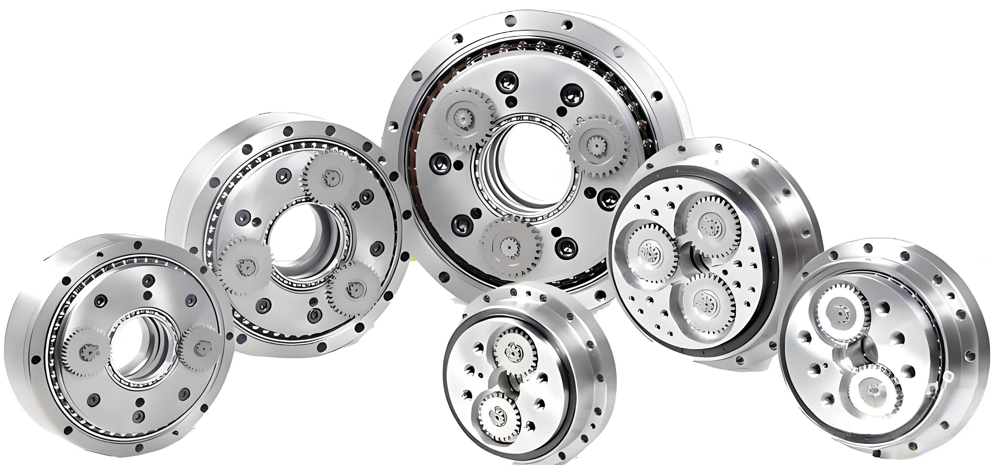
The cycloid gear in a rotary vector reducer operates on a principle combining cycloidal and planetary motions. Its unique tooth profile ensures multi-tooth simultaneous engagement, granting the reducer exceptional load capacity, high rigidity, and compact size. However, achieving the required micro-level precision (e.g., tooth profile error within ±3 µm and surface roughness Ra < 0.4 µm) post-hardening presents a significant manufacturing challenge. Form grinding emerges as the most suitable finishing process due to its ability to generate complex profiles with high accuracy and superior surface finish.
Fundamentals of Grinding and Form Grinding
Grinding is an abrasive machining process where material removal is accomplished by a rotating wheel composed of hard abrasive grains held by a bonding material. The process involves three fundamental interactions at the grain-workpiece interface: sliding (elastic deformation), plowing (plastic deformation without chip formation), and cutting (actual chip removal). The stochastic nature of grain distribution and protrusion height means all three mechanisms occur simultaneously across the grinding zone.
The key grinding parameters, collectively known as grinding conditions, are:
- Wheel Speed (vs): The peripheral velocity of the grinding wheel.
$$ v_s = \frac{\pi D n}{60 \times 1000} $$
where \( D \) is the wheel diameter (mm) and \( n \) is the rotational speed (rpm). - Workpiece Feed Rate (vw): The linear velocity of the workpiece relative to the wheel along the gear axis.
- Depth of Cut (ap): The nominal thickness of material removed per grinding pass, defined perpendicular to the workpiece surface. The actual depth achieved often deviates from the programmed value.
In form grinding of cycloid gears, a diamond dressing tool profiles the grinding wheel’s circumference to the exact conjugate shape of the gear tooth space. The wheel axis is perpendicular to the gear axis, and the profiled wheel is fed radially into the gear blank to grind the tooth flank. The accuracy of this process is paramount for the final performance of the rotary vector reducer.
Critical Factors Affecting Grinding Precision
The deviation between the programmed (theoretical) depth of cut and the actual depth achieved on the workpiece is a critical error metric. This error impacts final part dimensions, profile accuracy, and the efficiency of the finishing process. Excessive error leads to either under-grinding (requiring additional passes) or over-grinding (scrapping the part). The primary controllable factors influencing this error are the grinding parameters themselves, which interact in a complex manner.
1. Depth of Cut (ap): A larger nominal depth increases normal grinding forces. This accelerates abrasive grain wear, fracture, and bond breakage, leading to increased wheel wear. Consequently, the effective wheel diameter decreases during the pass, reducing the actual material removal rate and causing the achieved depth to be less than programmed. The relationship can be conceptually modeled as an efficiency factor, \( \eta \):
$$ a_{p,actual} \approx \eta(a_p, v_s, v_w) \cdot a_p $$
where \( \eta \) decreases with increasing \( a_p \) due to heightened wheel wear and possible machine/grinder deflection.
2. Wheel Speed (vs): Higher wheel speeds increase the number of active grains per unit time, reducing the undeformed chip thickness per grain. This lowers the force per grain, reducing wear and improving form-holding capability, which generally decreases depth error. However, beyond a critical speed, excessive heat generation and dynamic instabilities (vibration) can negate these benefits and increase error. The specific energy also interacts with speed:
$$ u \propto \frac{F_t v_s}{v_w a_p b} $$
where \( u \) is specific energy, \( F_t \) is tangential force, and \( b \) is width of cut. Optimizing \( v_s \) balances thermal damage and wheel wear.
3. Workpiece Feed Rate (vw): A lower feed rate increases the contact time per unit length, allowing for more complete material removal and often reducing depth error. However, it reduces productivity. The interaction with wheel speed is significant; a combination of high \( v_s \) and moderate \( v_w \) can maintain low error while improving throughput.
Experimental Methodology for Parameter Optimization
To systematically identify the optimal grinding parameter combination that minimizes depth-of-cut error for a cycloid gear made from hardened bearing steel (60 HRC), a designed experiment is essential. A precision gear grinding machine with verified kinematic accuracy and a dynamically balanced spindle is a prerequisite.
| Level | Wheel Speed, vs (m/s) | Feed Rate, vw (m/min) | Depth of Cut, ap (mm) |
|---|---|---|---|
| 1 | 31 (High) | 2.6 (High) | 0.060 |
| 2 | 27 (Medium) | 1.8 (Medium) | 0.030 |
| 3 | 23 (Low) | 1.0 (Low) | 0.010 |
A 3-factor, 3-level full factorial or orthogonal array design (e.g., L9 or L27) is appropriate. The response variable is the measured error:
$$ \Delta d = | a_{p,programmed} – a_{p,measured} | $$
Each test involves grinding a pre-machined gear blank with a consistent initial stock allowance, using a specified alumina wheel (e.g., 80 grit). Post-grinding, the actual removed stock is measured using a high-precision gear measuring center or coordinate measuring machine (CMM).
| Run | vs (m/s) | vw (m/min) | ap (mm) | Error, Δd (µm) |
|---|---|---|---|---|
| 1 | 31 | 2.6 | 0.060 | 5.3 |
| 2 | 31 | 1.8 | 0.060 | 4.2 |
| 3 | 31 | 1.0 | 0.060 | 2.7 |
| 4 | 27 | 2.6 | 0.060 | 4.5 |
| 5 | 27 | 1.8 | 0.060 | 4.1 |
| 6 | 27 | 1.0 | 0.060 | 1.2 |
| 7 | 23 | 2.6 | 0.060 | 7.1 |
| 8 | 23 | 1.8 | 0.060 | 6.1 |
| 9 | 23 | 1.0 | 0.060 | 5.6 |
| 10 | 31 | 2.6 | 0.030 | 2.5 |
Analysis of Results and Parameter Interaction
Analysis of Variance (ANOVA) and response surface methodology can be applied to the experimental data. The main effects and interaction effects of the three parameters on Δd are evaluated.
Main Effect Analysis:
- Depth of Cut (ap): The error Δd increases significantly with larger programmed depths. This confirms the dominant effect of increased wheel wear and process deflection at heavier cuts.
- Wheel Speed (vs): Higher wheel speeds consistently reduce error across different feed rates and depths of cut, up to the tested limit. This highlights the benefit of maintaining a high number of effective cutting edges.
- Feed Rate (vw): Lower feed rates tend to reduce error, but the effect is less pronounced than that of wheel speed and is highly dependent on the interaction with vs.
Interaction Effect Analysis: The optimal combination is not simply the “highest speed and lowest feed.” For a rotary vector reducer cycloid gear, the following guidelines can be derived:
- For Large Finishing Stock (ap ~ 0.06 mm): Use medium-to-high wheel speed (27-31 m/s) combined with a low-to-medium feed rate (1.0-1.8 m/min). This balances metal removal rate with wheel life and accuracy.
- For Medium Finishing Stock (ap ~ 0.03 mm): Medium wheel speed (27 m/s) is sufficient. A wider range of feed rates can be used, allowing for a trade-off between productivity and a marginal increase in error.
- For Final Spark-Out/Precision Stock (ap ≤ 0.01 mm): High wheel speed (31 m/s) and low feed rate (1.0 m/min) are critical to achieve minimal error (< 1 µm) and the required surface finish. This ensures the final dimensional and geometrical tolerances for the rotary vector reducer component.
The interaction can be modeled with a simplified phenomenological equation:
$$ \Delta d = k_0 + k_1 a_p + k_2 / v_s + k_3 v_w + k_{12} (a_p / v_s) + \epsilon $$
where \( k_i \) are coefficients determined via regression, and \( \epsilon \) encompasses other noise factors.
Advanced Considerations in Cycloid Gear Grinding
Beyond the basic grinding parameters, several advanced factors are crucial for the mass production of high-precision cycloid gears for rotary vector reducers.
1. Wheel Selection and Conditioning: The choice of abrasive (e.g., Al2O3, CBN), grain size, grade, and bond type must be tailored to the hardened steel. Cubic Boron Nitride (CBN) wheels, though costlier, offer vastly superior wear resistance, maintaining form accuracy over long batches and reducing dressing frequency. The dressing process itself—diamond roll form, overlap ratio, and dressing speed—must be rigorously controlled to impart and maintain the precise cycloidal profile on the wheel.
2. Thermal Management and Grinding Fluids: Grinding generates substantial heat, risking thermal damage (burn, tempering, residual tensile stresses) to the gear’s surface layer. This is catastrophic for a rotary vector reducer gear’s fatigue life. Effective high-pressure coolant application is non-negotiable. The fluid must provide excellent lubrication to reduce grinding forces, efficient cooling to remove heat, and effective cleaning to prevent wheel loading. Synthetic or semi-synthetic fluids with extreme pressure additives are typically employed.
3. Process Stability and In-Process Monitoring: Achieving consistent sub-micron accuracy requires a stable process. This involves monitoring spindle vibration (should be < 0.02 mm/s), coolant temperature control, and compensation for machine thermal growth. In-process gaging systems can be integrated to measure gear dimensions after roughing and semi-finishing passes, allowing for adaptive adjustment of the final grinding parameters to hit the target size automatically, compensating for wheel wear and other drift factors.
4. Grinding Strategy: A multi-stage strategy is optimal:
- Roughing: Higher ap, higher vw to remove bulk stock efficiently.
- Semi-Finishing: Reduced ap and vw to correct geometry and prepare for finishing.
- Finishing: Very low ap, optimized vs and vw (as determined by experiment) to achieve final size and roughness.
- Spark-Out: Several passes with no incremental infeeding (ap=0) to eliminate system deflection and improve roundness/profile.
This strategy maximizes both productivity and final quality of the rotary vector reducer gear.
Conclusion
The precision grinding of cycloid gears is a sophisticated manufacturing process that directly underpins the performance of high-end rotary vector reducers. While high machine tool accuracy is a prerequisite, mastering the grinding process is the key to achieving the requisite micro-geometry and surface integrity. The programmed depth of cut, wheel speed, and feed rate are primary interactive variables controlling the error between intended and actual material removal. Through systematic design of experiments—factorial or orthogonal arrays—the optimal parameter combination for different stages of finishing can be empirically determined, balancing accuracy, wheel life, and productivity.
Successful production extends beyond parameter optimization. It encompasses the judicious selection of grinding wheel and coolant, precise wheel conditioning, thermal and stability management, and the implementation of a multi-stage grinding strategy with potential adaptive control. By rigorously addressing these factors, manufacturers can overcome the technological barriers in producing high-precision cycloid gears, enabling the reliable and widespread adoption of domestically produced rotary vector reducers in advanced robotics and precision automation systems.