
The pursuit of high-precision, quiet-running, and cost-effective power transmission continues to drive advancements in gear manufacturing. Among the various finishing processes, gear shaving stands out as a pre-hardening finishing operation of paramount importance. The primary objective of gear shaving is to elevate the gear quality one to two grades above the final drawing requirement before heat treatment. This strategic approach effectively corrects short-period errors inherited from pre-shaving processes, such as profile deviations and base pitch deviations, while simultaneously reducing meshing noise. From a technical standpoint, this non-grinding route eliminates the risk of grinding cracks on the tooth flanks. Economically, the process cost of gear shaving is remarkably low, often less than one-tenth of that of gear grinding, making it a consensus choice within the gear industry for a wide range of applications.
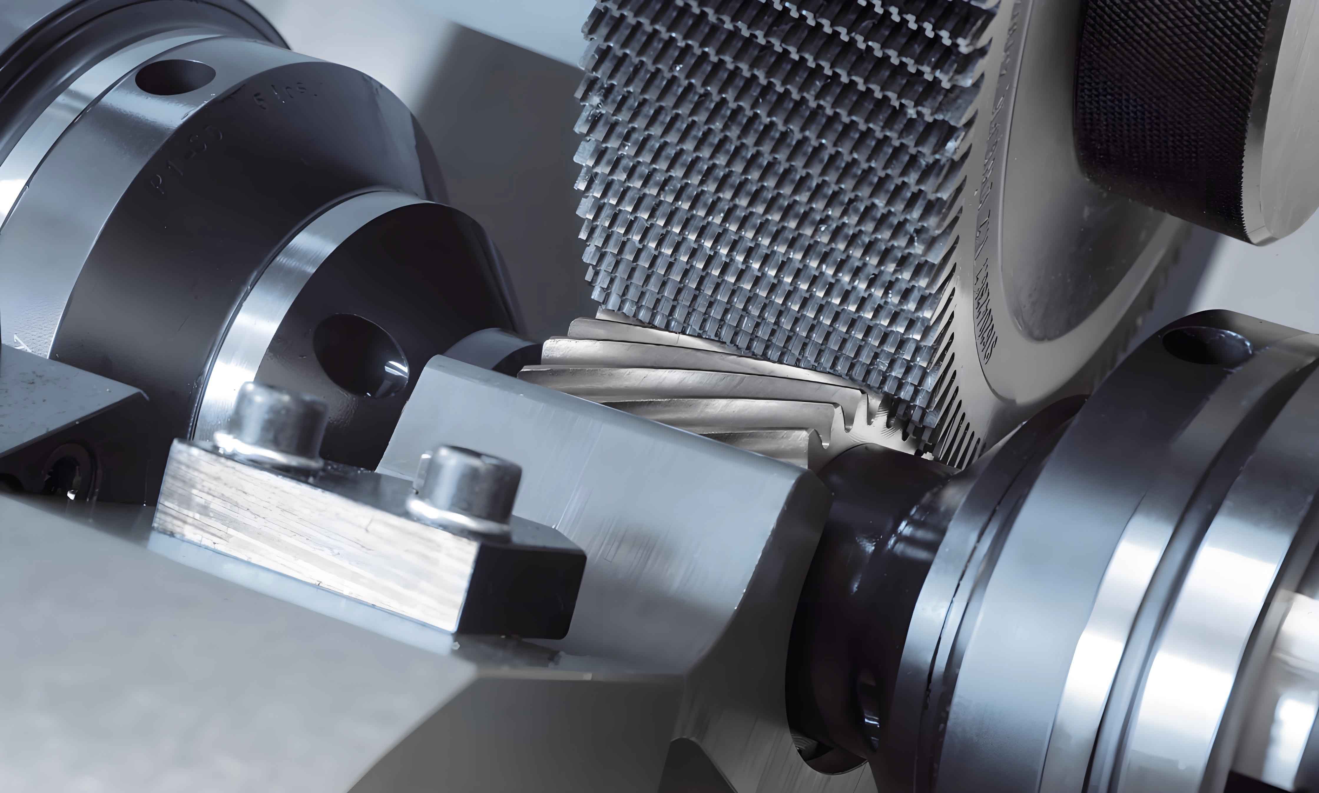
The widespread adoption of gear shaving is supported by specialized tooling. The tubular fixture, also known as a top-sleeve fixture, has seen significant promotion and application due to its superior performance over traditional designs. It offers exceptional positioning accuracy, rigidity, service life, and reliability. This fixture typically centers a gear blank using its bore diameter. However, a specific challenge arises when applying this highly effective fixture design to gears featuring a non-circular internal feature, such as a rectangular splined hole. For such components, the fixture must adapt to center the blank using the spline’s minor diameter. During the gear shaving process, the contact line between the splined hole and the shaving mandrel is not constant; it changes in real-time as the blank rotates. This dynamic interaction induces a variation in the center distance between the gear blank and the shaving cutter, which, in turn, introduces a specific form of geometric eccentricity. This eccentricity component, inherent to the spline geometry and its fit with the mandrel, can potentially influence the final accuracy of the shaved gear. Therefore, it is essential to quantitatively investigate the laws governing this center distance variation, assess its impact on geometric eccentricity, and develop economical and rational strategies for applying the tubular gear shaving fixture to rectangular spline-hole gears while effectively controlling associated machining errors.
Analysis of Center Distance Variation in Rectangular Spline-Hole Shaving
The adaptation of the tubular fixture for gears with rectangular internal splines involves a minor-diameter centering scheme. The core components remain a mandrel, a support washer, a clamping sleeve, and the top sleeve itself. During operation, all fixture components rotate with the shaving cutter. The gear blank is located on the cylindrical mandrel via its spline’s minor diameter. Under the combined action of the blank’s own weight and the radial cutting force of the gear shaving process, a unilateral clearance exists in the locating pair, consistently positioned at the bottom. The axial clamping force from the spring and the three-point support from the washer significantly reduce clamping deformation of the blank. The fundamental difference from machining a plain bore gear lies in the geometry of the rectangular spline hole, which features evenly distributed keyways and chamfers. This geometry prevents continuous contact along the mandrel’s top generatrix and results in a clearance that is neither constant nor uniformly distributed.
Standard specifications, such as GB/T 1144-2001, define tolerance zones for the minor diameter fit between internal and external splines. Common fit designations for general drive applications include H7/f7, H7/g7, and H7/h7. For precision drives, tighter fits like H5/f5 or H6/g6 are specified. In the context of gear shaving, achieving mandrel accuracy grades like f7 or even f5 is technically feasible. To analyze the effect of fit clearance on center distance variation and shaving quality, we consider an external gear with a rectangular spline specification of N×d×D×B = 6×26×30×6, examining fits of H7/f7 and H7/f5.
The real-time contact between the blank and the mandrel, driven by gravity and cutting forces overcoming face friction, is key to understanding the dynamic variation. To model this using an analytical method, we consider a cross-sectional view. For analytical convenience, we initially assume the spline hole axis is fixed and the mandrel axis is floating. Let the point of contact on the cross-section be the origin for a circle with a radius equal to the actual mandrel radius, \(d_s/2\). This circle intersects the Y-axis at point \(O’\). The angle between this radius line and the Y-axis is denoted as \(\theta\). The coordinates of the mandrel’s center in this coordinate system are:
$$
x_s = 0
$$
$$
y_s = \frac{d_h}{2} – H_h – \frac{d_s}{2 \cos\theta}
$$
Here, \(d_h\) is the actual minor diameter of the spline hole, \(d_s\) is the actual diameter of the mandrel, and \(H_h\) is the height difference between the contact line and the top generatrix of the spline’s minor diameter. Since \(H_h = \frac{d_h}{2} – \sqrt{(\frac{d_h}{2})^2 – (\frac{d_s}{2}\sin\theta)^2}\), the expression for \(y_s\) can be rewritten as:
$$
y_s = \sqrt{ \left( \frac{d_h}{2} \right)^2 – \left( \frac{d_s}{2} \sin\theta \right)^2 } – \frac{d_s}{2 \cos\theta}
$$
To reflect the actual condition where the mandrel axis is fixed and the blank axis floats, the variation in center distance \(A\) between the gear blank and the shaving cutter is derived from the movement of the blank’s center:
$$
A = y_h = -y_s = \frac{d_s}{2 \cos\theta} – \sqrt{ \left( \frac{d_h}{2} \right)^2 – \left( \frac{d_s}{2} \sin\theta \right)^2 }
$$
When contact occurs on the circular arc of the minor diameter (analogous to a plain bore), \(\theta = 0\). Substituting into the equation yields \(A = (d_s – d_h)/2\), representing a constant center distance. For the general case where contact occurs elsewhere, the correct formulation for the center distance variation \(\Delta A\) relative to a nominal position is:
$$
\Delta A(\theta) = \frac{d_h}{2} + \frac{d_s}{2} (\cos\theta – 1) – \sqrt{ \left( \frac{d_h}{2} \right)^2 – \left( \frac{d_s}{2} \sin\theta \right)^2 }
$$
This equation reveals that the actual diameters of the spline hole and mandrel directly influence the variation. Crucially, the range of \(\theta\) is dictated by the spline’s structural dimensions: the number of keys \(N\), the keyway width \(B\), and the chamfer size \(C\). These parameters define the angular sectors where contact transitions from the circular arc to the chamfer or keyway face. The relationship \(B + 2C << d_s \cos(45^\circ)\) typically ensures contact occurs at the chamfer’s sharp corner, not along its slope.
Graphical Simulation and Influence of Fit Clearance
The mathematical model, while precise, does not intuitively display the magnitude of variation. Therefore, graphical simulation based on MATLAB software is employed to visualize the impact of maximum, minimum, and average fit clearances for the two selected fit designations: H7/f7 and H7/f5. These clearances correspond to different states of tooling wear: maximum clearance occurs with a new broach and a mandrel at its wear limit; minimum clearance with a broach at its re-grind limit and a new mandrel; and average clearance with both tools near the middle of their tolerance bands.
For the 6×26×30×6 spline, the relevant clearances are:
| Fit Designation | Maximum Clearance (X_max) mm | Minimum Clearance (X_min) mm | Average Clearance (X_avg) mm |
|---|---|---|---|
| H7/f7 | 0.062 | 0.020 | 0.041 |
| H7/f5 | 0.050 | 0.020 | 0.035 |
The simulation over one spline pitch (\(\pi/3\) radians) and one full revolution (\(2\pi\) radians) reveals a critical insight. The rectangular spline structure introduces a new, periodic geometric eccentricity component \(e_F\) with a period of \(\pi/3\). The amplitude of \(e_F\), defined as half the peak-to-peak variation of \(\Delta A(\theta)\), is significantly smaller than the nominal fit clearance \(X\). Furthermore, the difference in \(e_F\) amplitude between the H7/f7 and H7/f5 fits is much smaller than the difference in their \(X_{max} – X_{min}\) values. This quantitatively demonstrates the beneficial effect of the tubular fixture’s operational principle: the dynamic, single-sided contact minimizes the translation of nominal radial clearance into actual axis offset. The simulation results can be summarized as follows:
| Condition (6×26×30×6) | Amplitude of e_F (mm) | Notes |
|---|---|---|
| H7/f7 @ X_max | ~0.0011 | Largest observed variation |
| H7/f5 @ X_max | ~0.0007 | Tighter fit reduces variation |
| H7/f7 @ X_min | ~0.0003 | Minimal variation even for looser fit |
| H7/f5 @ X_min | ~0.0003 | Same as H7/f7 at minimum clearance |
To generalize, a larger spline size (e.g., 6×28×34×7) with increased minor diameter, keyway width, and chamfer will have a slightly larger permissible \(\theta\) range. Simulation for this size confirms that while \(e_F\) increases modestly, the fundamental relationship holds: its value remains small and the difference between fits is limited. This indicates good stability of the center distance variation mechanism for the tubular gear shaving fixture across different spline specifications, suggesting that moderately worn mandrels could theoretically function. However, this conclusion requires careful qualification considering wear effects on form error.
Impact of Center Distance Variation on Shaved Gear Accuracy and Resulting Eccentricity
The total geometric eccentricity \(e_{1(spline)}\) present during the gear shaving of a spline-hole gear using a tubular fixture is a root-sum-square combination of multiple contributing factors:
$$
e_{1(spline)} = \sqrt{ e_E^2 + e_D^2 + e_F^2 }
$$
Where:
- \(e_E\) is the eccentricity caused by misalignment (e.g., coaxiality error) between the mandrel axis and the line connecting the shaving machine’s headstock and tailstock centers.
- \(e_D\) is the eccentricity induced by distortion of the gear blank due to clamping forces.
- \(e_F\) is the periodic eccentricity component arising from the center distance variation due to the spline geometry, as derived and simulated previously.
Compared to shaving a plain bore gear where \(e_{1(plain)} = \sqrt{ e_E^2 + e_D^2 }\), the spline-hole gear experiences an additional, albeit small, component \(e_F\). The influence of this component on key gear accuracy parameters is analyzed below.
1. Increase in Radial Runout (ΔFr)
In theory, the radial runout of the gear teeth is approximately twice the total geometric eccentricity: \(\Delta F_r \approx 2 e_{1(spline)}\). Since \(e_{1(spline)} > e_{1(plain)}\), it follows that \(\Delta F_r\) for the spline-hole gear will be larger. Radial runout primarily affects the accuracy of motion transmission (single-flank accuracy), which is critical for gears operating with minimal backlash. The increase, while potentially small from \(e_F\) alone, contributes to the overall error budget.
2. Increase in Total Cumulative Pitch Deviation (ΔFp)
The total cumulative pitch deviation, a key measure of kinematic accuracy, is empirically related to radial runout and gear width. A common approximation is \(\Delta F_p \approx 0.8 (\Delta F_r + \Delta F_W)\), where \(\Delta F_W\) is the variation in base tangent length (span measurement). Geometric eccentricity affects both terms. Firstly, as established, \(\Delta F_r\) increases. Secondly, the variable cutting depth caused by the eccentricity alters the tooth thickness symmetrically. The relationship between eccentricity \(e\) and base tangent length variation is \(\Delta F_W \approx 4 e \sin(\alpha)\), where \(\alpha\) is the pressure angle. Therefore, an increase in \(e_{1(spline)}\) directly increases \(\Delta F_W\), which in turn exacerbates the increase in \(\Delta F_p\), further degrading motion transmission accuracy.
3. Influence on Pitch Deviations and Transmission Smoothness
The periodic nature of \(e_F\) means the center distance variation, and thus the effective bore geometry experienced by the shaving cutter, follows a repeating pattern. This pattern can be expressed as a Fourier series expansion of the bore’s effective radius \(R(\theta)\):
$$
R(\theta) = \frac{1}{2\pi} \int_{0}^{2\pi} R(\theta) d\theta + \sum_{k=1}^{\infty} C_k \cos(k\theta + \psi_k)
$$
The first term is the average radius of the effective bore, while the summation represents harmonic components (lobing). The primary harmonic from the spline structure has a frequency of \(k = N\) (the number of splines). This effectively imparts a low-amplitude, multi-lobe form error to the gear’s axis of rotation during shaving. This error causes a time-varying instantaneous transmission ratio during subsequent gear operation, which can slightly increase noise levels, vibration, and impact. The resulting pitch deviation errors are distributed with a phase related to the spline’s orientation, making them a source of structured, rather than purely random, excitation that can broaden the noise spectrum of the gear pair.
Control Strategies for Precision in Shaving Rectangular Spline-Hole Gears
To harness the benefits of the tubular gear shaving fixture for spline-hole gears while mitigating the aforementioned accuracy risks, a comprehensive control strategy targeting each component of the total geometric eccentricity \(e_{1(spline)}\) is essential.
1. Controlling Mandrel-Related Eccentricity (e_E)
Minimizing \(e_E\) requires exceptional precision in the fixture’s construction and alignment.
- Precision Fits: The running fit between the mandrel and the clamping sleeve must be tightly controlled using selective assembly or high-precision manufacturing to minimize radial play that could lead to axis tilt.
- Center Hole Integrity: The geometric accuracy of the center holes on both the mandrel and the top sleeve is paramount. Employing CNC center hole grinding processes ensures these critical datum features are near-perfect, minimizing runout of the entire fixture assembly when mounted between the machine centers.
- Assembly Verification: The complete fixture assembly should be verified for radial runout of the mandrel’s locating diameter. A typical requirement, aligned with the accuracy standards of horizontal shaving machines, is a total indicator reading (TIR) not exceeding 0.005 mm when the fixture is mounted on an inspection arbor or directly in the machine.
2. Minimizing Blank Distortion Eccentricity (e_D)
The tubular fixture inherently reduces \(e_D\) compared to solid clamping methods, but blank quality is crucial.
- Blank Manufacturing Process: For a plain bore gear, turning the bore and the mounting face in one setup ensures perfect perpendicularity. For a spline-hole gear, the sequence is different: the spline is typically broached after rough machining. To achieve the required gear blank accuracy (usually 1-2 grades finer than the gear itself), a secondary finishing operation is necessary. After broaching, the blank should be finished using the spline’s minor diameter for centering (e.g., on a mandrel) to grind or turn the mounting face(s) and the outside diameter. This guarantees the mounting face’s flatness and its perpendicularity to the minor diameter axis.
- Fixture Interface Quality: High-precision blanks must mate with equally precise fixture surfaces. The support washer and the clamping sleeve face should have minimal face runout (e.g., ≤ 0.005 mm TIR) to ensure uniform, distortion-free clamping of a well-prepared blank under the machine’s axial load.
The eccentricity due to distortion can be estimated by \(e_D = (\Delta D \cdot b) / d_1\), where \(\Delta D\) is the clamping deformation, \(b\) is the facewidth, and \(d_1\) is the supporting face diameter. Controlling \(\Delta D\) through precision blanks and fixtures directly reduces \(e_D\).
3. Managing Spline-Induced Periodic Eccentricity (e_F) and Overall Strategy
The simulation indicates that \(e_F\) itself is small and stable across fits and spline sizes. However, its contribution is not negligible in high-precision contexts. More importantly, the dynamic contact imposes repeated impact loads on the mandrel.
- Optimal Fit Selection: While both H7/f7 and H7/f5 are usable, specifying a tighter fit like H7/f5 (or even H6/f5 for precision drives) is recommended. This reduces the maximum possible \(e_F\) and, more critically, provides a more constrained and stable running condition for the blank, potentially improving process consistency.
- Mandrel Condition Monitoring: The conclusion that a worn mandrel is “usable” based solely on \(e_F\) stability is misleading. Wear will not be uniform; it will be accentuated at the frequent contact points, degrading the mandrel’s roundness and cylindricity. A mandrel with significant form error will cause center distance variations even in the circular arc contact zones, potentially generating an \(e_F\) component far larger than that predicted by the spline geometry model. Therefore, a strict policy against using mandrels showing measurable wear or loss of form is necessary to maintain gear shaving精度.
- Holistic Process Control: The final shaved gear quality is a function of the entire system. Prioritizing high fixture accuracy (low \(e_E\)), supplying precision blanks (low \(e_D\)), selecting an appropriate spline fit, and maintaining pristine mandrel condition are interdependent strategies that collectively ensure the synthesized eccentricity \(e_{1(spline)}\) remains within acceptable limits to yield gears that meet the pre-hardening quality target of 1-2 grades above the final specification.
Conclusion
The application of the tubular, or top-sleeve, fixture for the gear shaving of gears with rectangular internal splines is a viable and advantageous process when accompanied by a thorough understanding and control of the associated geometric errors. Analytical modeling and simulation confirm that the spline geometry introduces a periodic component \(e_F\) to the total geometric eccentricity due to real-time changes in the center distance between the gear blank and the shaving cutter. Crucially, the amplitude of this component is significantly attenuated compared to the nominal radial clearance of the spline fit, a benefit derived from the fixture’s dynamic single-sided contact operation. While \(e_F\) is relatively small and stable across different spline fits and sizes, it nevertheless contributes to increases in radial runout, cumulative pitch deviation, and can influence transmission smoothness.
The successful implementation of this gear shaving strategy hinges on a multi-faceted precision control policy. This policy must aggressively minimize the other, typically larger, contributors to eccentricity: mandrel alignment error (\(e_E\)) and blank clamping distortion (\(e_D\)). This is achieved through ultra-precise fixture manufacturing, verification of assembly runout, and the supply of gear blanks with mounting faces finished relative to the spline’s minor diameter. Furthermore, specifying a relatively tight spline fit (e.g., H7/f5) and, most importantly, strictly avoiding the use of mandrels with significant wear or form error are essential practices. A worn mandrel can induce eccentricity variations that dwarf those caused by the spline geometry itself. By adhering to these strategies, the inherent economic and technical benefits of the gear shaving process can be fully realized for rectangular spline-hole gears, producing high-quality components capable of meeting stringent post-heat treatment performance requirements.