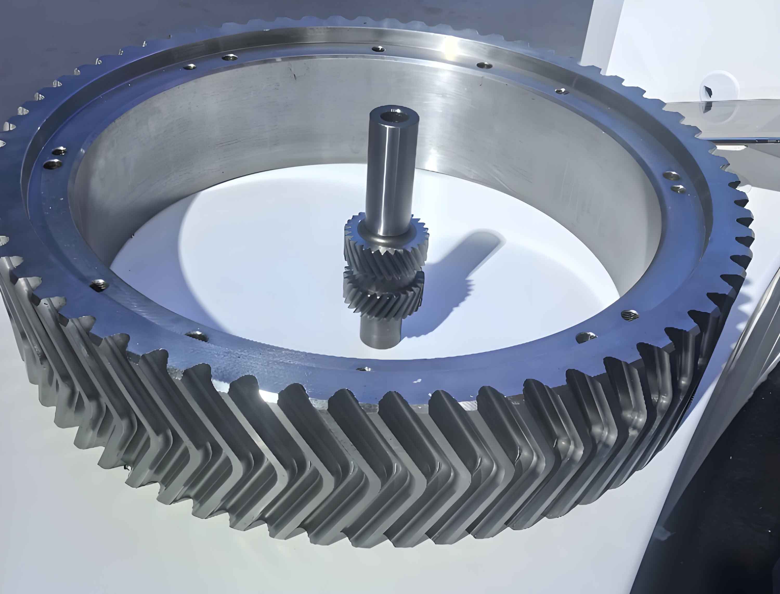
Structural Characteristics of Herringbone Gears
The unique double-helical configuration of herringbone gears provides exceptional mechanical advantages expressed by:
$$P_{trans} = \frac{2\pi n T}{60} \cdot \eta_{hb}$$
Where:
\(P_{trans}\) = Transmitted power (kW)
\(n\) = Rotational speed (rpm)
\(T\) = Torque (Nm)
\(\eta_{hb}\) = Herringbone gear efficiency (typically 0.98-0.995)
| Parameter | Straight Gear | Herringbone Gear |
|---|---|---|
| Axial Force | High | Near Zero |
| Contact Ratio | 1.4-1.6 | 2.0-2.8 |
| Noise Level (dB) | 75-85 | 60-70 |
Critical Manufacturing Parameters
The wear resistance of herringbone gears can be modeled using Archard’s equation:
$$W = \frac{k \cdot L \cdot H}{K}$$
Where:
\(W\) = Wear volume (mm³)
\(k\) = Wear coefficient
\(L\) = Load (N)
\(H\) = Sliding distance (m)
\(K\) = Material hardness (MPa)
| Module (mm) | Tooth Depth (mm) | Cutting Speed (m/min) | Feed Rate (mm/rev) |
|---|---|---|---|
| 14-16 | 32.5±0.05 | 25-30 | 0.15-0.25 |
| 16-20 | 37.5±0.06 | 20-25 | 0.10-0.20 |
Advanced Machining Strategies
The thermal deformation compensation model for large-module herringbone gears during machining:
$$\Delta D = \alpha \cdot D \cdot \Delta T + \beta \cdot \frac{P_c}{k} \cdot t^{0.5}$$
Where:
\(\Delta D\) = Diametral deformation (μm)
\(\alpha\) = Thermal expansion coefficient
\(D\) = Nominal diameter (mm)
\(\Delta T\) = Temperature variation (°C)
\(\beta\) = Cutting force coefficient
\(P_c\) = Cutting power (W)
\(k\) = Thermal conductivity (W/m·K)
Precision Control Methodology
| Process Stage | Tolerance (μm) | Surface Finish Ra (μm) | Tool Wear Limit |
|---|---|---|---|
| Rough Cutting | ±80 | 3.2-6.3 | 0.3mm |
| Semi-finishing | ±40 | 1.6-3.2 | 0.15mm |
| Finish Cutting | ±15 | 0.8-1.6 | 0.05mm |
Dynamic Stability Analysis
The critical rotational speed for herringbone gear shafts considering torsional vibration:
$$N_{cr} = \frac{30}{\pi} \sqrt{\frac{GJ}{I_p L^2}} \cdot \sqrt{1 + \frac{k_m L^2}{GJ}}$$
Where:
\(N_{cr}\) = Critical speed (rpm)
\(G\) = Shear modulus (GPa)
\(J\) = Polar moment of inertia (mm⁴)
\(I_p\) = Mass moment of inertia (kg·m²)
\(L\) = Shaft length (m)
\(k_m\) = Meshing stiffness (N/m)
Process Optimization Matrix
| Parameter | Weight Factor | Optimum Range | Quality Impact |
|---|---|---|---|
| Tool Geometry | 0.25 | Rake Angle 8°-12° | ±0.3μm |
| Coolant Pressure | 0.18 | 15-20 bar | ±0.2μm |
| Cutting Temperature | 0.22 | 80-120°C | ±0.4μm |
