
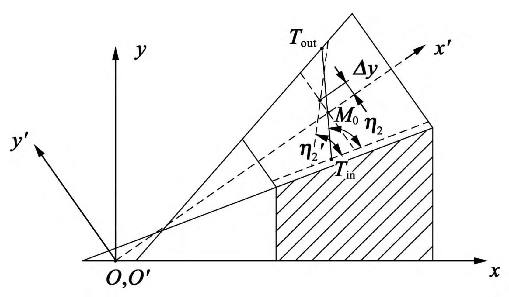
The main indexes of meshing performance of spiral bevel gears include transmission error, tooth surface impression and design coincidence degree. Among them, the design parameters of transmission error mainly include the amplitude of meshing conversion point and the symmetry of transmission error curve. Among them, the amplitude of meshing conversion point determines the impact force and stability of meshing tooth pair during tooth replacement; The symmetrical transmission error can avoid premature edge contact under medium and light load. In order to make the gear pair transmission more stable, at least two pairs of teeth are required to mesh at the same time under the working load. By actively designing the contact path of spiral bevel gear as a straight line, the sensitivity of meshing performance to installation error and the requirements of installation accuracy can be reduced. Figure 1 shows the parameters of the local synthesis method on the rotating projection plane, including the direction angle of the contact path η 2. Location of design reference point M0( Δ x, Δ y) The value m’21 for the first-order derivation of the reciprocal of the transmission ratio.
The design process of processing parameters of spiral bevel gear presets the design coincidence degree ε r. The transmission error amplitude of meshing conversion point and the symmetry of curve shape are as follows:
(1) Parameters of local synthesis method for given design reference point M0( η 2, Δ x, Δ y. M’21), with the help of the active design of spiral bevel gear, the machining parameters of large and small wheels are obtained [13] 156-157. Amplitude of meshing conversion point δφ 2 is determined by the first derivative m’21 of the reciprocal of the transmission ratio, and its value is generally determined according to the conditions such as no edge contact of the working load and minimum bearing transmission error.
(2) The meshing position t0 of the design reference point M0 is directly calculated by the local synthesis method. According to the geometric conditions of meshing between the top of big gear and the root of small gear, the meshing position tin can be calculated; Similarly, the meshing position tout can be calculated from the geometric conditions of meshing between the top of the pinion and the root of the gear. The specific process is as follows:
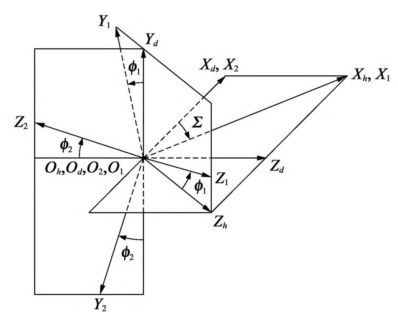
Given the machining parameters of large and small wheels, the tooth surface position vector and normal vector of large and small wheels obtained by meshing equation and coordinate transformation are R (1) respectively θ p, ϕ p)、n(1 θ p, ϕ p) And R (2) θ g, ϕ g)、n(2 θ g, ϕ g)。 Fig. 2 shows the meshing coordinate system for geometric contact analysis of spiral bevel gear tooth surface, where S1 is the pinion coordinate system; S2 is the large wheel coordinate system; SH is a fixed coordinate system. The basic equations of TCA in the fixed coordinate system can be expressed as:
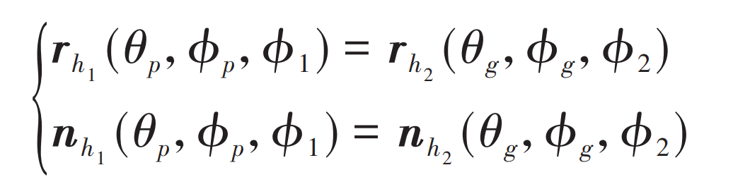
Where, Rh1 and Rh2 are the position vectors of small wheel and large wheel in SH respectively; Nh1 and NH2 are the unit normal vectors of small wheel and large wheel in SH respectively; θ p、 ϕ P is the tooth surface parameter of small wheel; θ g、 ϕ G are the parameters of gear tooth surface; ϕ 1、 ϕ 2 is the meshing angle of small wheel and large wheel respectively.
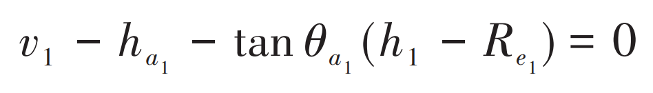
When the contact point is on the top line of the big gear, it means that the tooth root of the driving small wheel drives the top of the driven big gear to make the gear pair enter the meshing state. The geometric conditions are as follows:
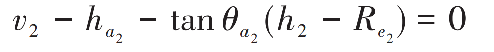
Where, V2 and H2 are the position parameters of the contact point of the spiral bevel gear tooth surface on the rotating projection surface of the large wheel, which can be expressed as:
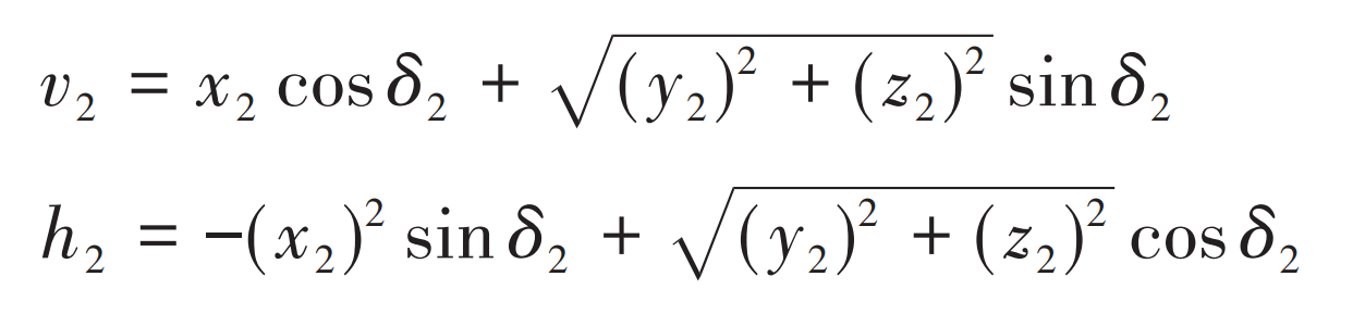
Where X2, Y2 and Z2 are the coordinate components of the contact point of the gear tooth surface respectively; δ 2 is the cone angle of large wheel joint; θ A2 is the top angle of gear teeth; HA2 is the tooth top height of the big end of the big wheel; Re2 is the outer cone distance of the large wheel.
When the contact point is on the tooth top line of the spiral bevel gear pinion, it means that the tooth top of the driving pinion drives the tooth root of the driven pinion, so that the spiral bevel gear pair will exit the meshing state. Its geometric conditions are as follows:
Where, V1 and H1 are the position parameters of the tooth surface contact point on the rotating projection surface of the small wheel, which can be expressed as:
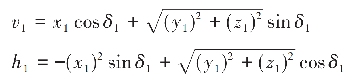
Where x1, Y1 and Z1 are the coordinate components of the contact point of the spiral bevel gear pinion tooth surface respectively; δ 1 is the cone angle of small wheel joint; θ A1 is the tooth apex angle of spiral bevel gear; HA1 is the tooth top height of the big end of the small wheel; RE1 is the outer cone distance of the small wheel. The joint solution formula can obtain the meshing position tin; The meshing position tout can be obtained by solving the formula simultaneously.
(3) Define symmetry ς Is the ratio of the engagement time | tin-t0 | and the engagement time | t0 tout | when symmetrical ς The closer to 1, the closer tin is to tout. Since the selection of design reference point M0 is arbitrary, generally speaking, for the degree of symmetry ς= 1 it is difficult to determine; Therefore, in order to achieve the required position symmetry, we usually adjust the tooth height position of spiral bevel gear at the design reference point M0 Δ Y method.
(4) In order to design, a satisfactory coincidence degree is defined ε r. When the meshing type is single tooth meshing of spiral bevel gear driving wheel, the coincidence degree ε R is the ratio of the total meshing time | tin tout | of the driving wheel from meshing in to meshing out to the meshing cycle tmesh. Calculated by TCA, when ε R is greater than (less than) the predetermined design coincidence degree ε 0, you can increase (decrease) the direction of the contact trace η 2. It is used to obtain the design coincidence degree that meets the requirements.