The “electronic gearbox” was put forward by the British in the s. The purpose is to replace the mechanical transmission mechanism with the electrical automatic control technology, so as to obtain high precision and high quality machining.
It includes the following parts: (1) main motion detection feedback device; (2) slave motion detection feedback device; (3) signal processing module; (4) slave motion execution module, etc.
The main motion detection device realizes the detection of the position or speed of the main motion, which is composed of encoder, resolver, circular (linear) inductosyn, speed generator and other detection elements.
The detection of the actual position or speed signal of the slave motion is realized from the motion detection device, and the detection element is the same as above.
The signal processing module realizes the processing of command signal and feedback signal, and controls and drives the two signals to move from the moving device through certain regular processing.
The slave motion execution module can be servo AC (DC) current motor, linear motor or other motion devices and mechanisms.
The motion information of the main motion and the slave motion is obtained by each automatic detection device respectively, and then the signal processing control module processes the two kinds of information according to a certain rule, and uses the processed information to control the slave motion actuator to track the main motion strictly according to the rule.
In the electronic gearbox, the main motion is not controlled, only the motion information is detected, but the slave motion needs closed-loop control. The master and slave motion can be linear motion, rotary motion or other motion respectively. As long as there is a strict motion relationship between them, the electronic gearbox can be used.
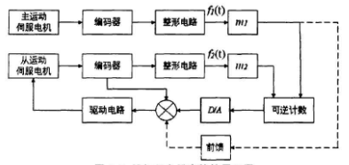
Figure is the schematic diagram of the electronic gearbox realized by the theory of phase-locked loop. The main motion and the slave motion are rotary motion, the controlled object is motor, the detection device of the main and the slave motion adopts pulse encoder, the signal processing and driving module includes two frequency multipliers, phase comparison device, conversion circuit and servo amplifier circuit. The dotted line in the figure shows the feedforward compensation circuit.