
Because the coincidence degree of helical gear is not an integer, its meshing transmission process is alternating between single and double tooth meshing. At the same time, many factors such as the deformation of gear teeth in the meshing process and the base pitch error caused by the bending and torsion deformation of helical gear shaft will cause the meshing in and meshing out impact of helical gear in the meshing process. As the helical gear rotates, the teeth enter the meshing along the meshing line. As shown in the figure, the abscissa is the actual meshing line and the ordinate is the corresponding load value. The starting point of the meshing cycle of the gear tooth is the point of the meshing line of the gear tooth.
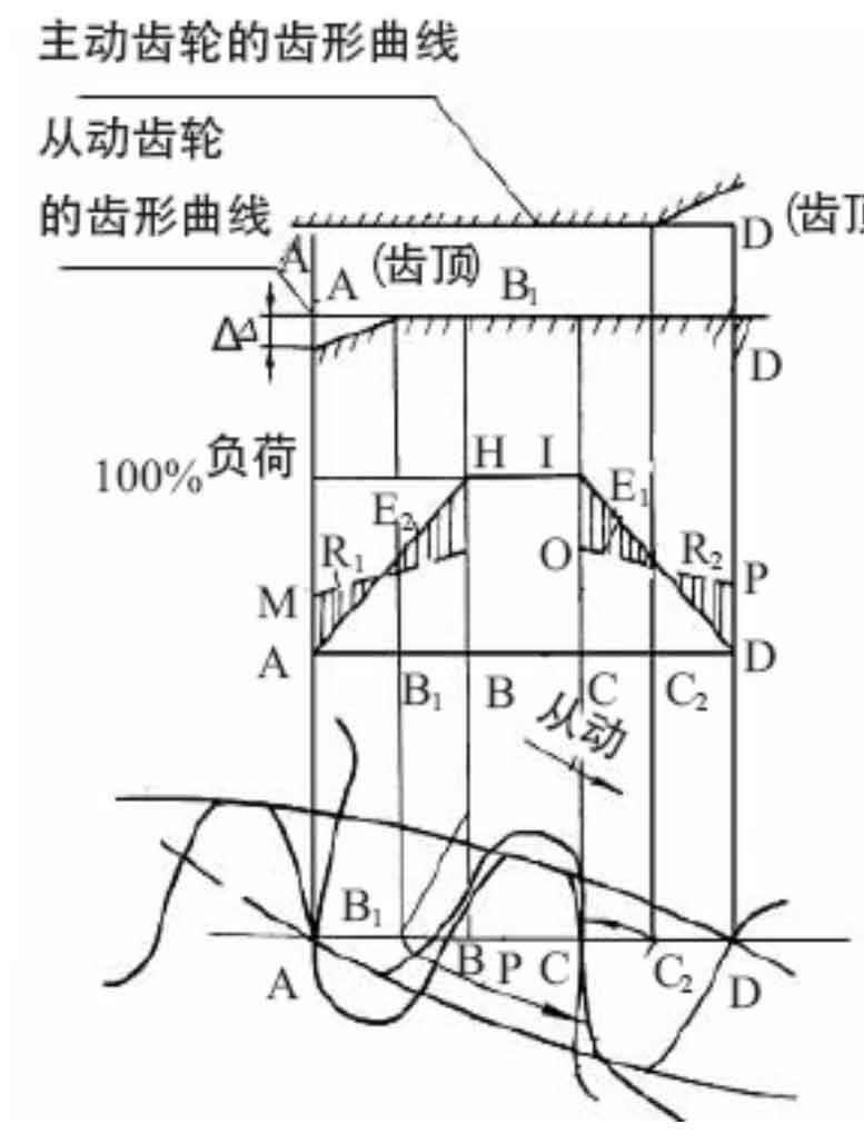
AB and CD segments are double tooth meshing area, and BC segment is single tooth meshing area. Single tooth meshing and double tooth meshing are carried out alternately, so the load on each tooth is fluctuating, the load distribution is uneven and accompanied by obvious mutation. Due to the contact, bending and shear deformation in the meshing process, the load change is mitigated, and the actual load distribution is amnhipd. The load shares about 40% of the total load at point a just entering the meshing time. At the transition point B from the double tooth meshing area to the single tooth meshing area, the load shared by point B is about 60% of the total load. Then it quickly turns to the single tooth meshing area. At this time, it reaches 100% load, and finally the load shared by point D is about 40%.
According to the above analysis, the load distribution of the helical gear has an obvious mutation in the meshing process, the deformation of the helical gear also changes accordingly, and the meshing interference will occur when the helical gear is meshed. Tooth profile modification is mainly to properly cut off a part of the interfering tooth surface from the tooth profile of the helical gear, and improve the uneven load distribution and mutation phenomenon by changing the involute of the helical gear. During tooth profile modification, a section equal to the base section along the meshing line is not modified, that is, the b1c2 section of the single tooth meshing area in the figure is not modified, so as to ensure that the coincidence degree of the helical gear is greater than 1; The modification lengths of the meshing in end and the meshing out end are equal, that is, the double tooth meshing areas Ab1 and C2D in the figure are equal. After modification, the ideal load distribution law of gear teeth is ahid, so that the gear teeth just contact at the meshing point a, the load drops from m to zero, and then gradually increases to H point to reach 100% load. In the CD section, the load gradually decreases from 100% to zero at point D.
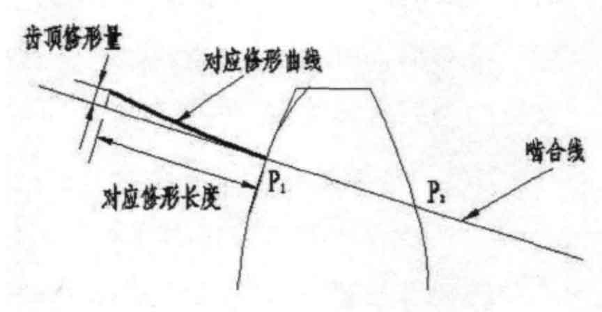
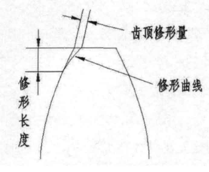
In the tooth profile modification, in order to clearly represent the modification position and the corresponding modification amount of the helical gear, the following two ways are usually used: first, the modification amount of the tooth profile position is expressed as the function of the tooth profile curvature radius or pressure angle of the point, which mostly appears in the form of discrete point coordinates, which is convenient for the processing and use of the helical gear; Second, the position of tooth profile modification and the normal modification amount of tooth profile are indicated on the meshing line of helical gear pair. This method can better analyze the influence of tooth modification on helical gear meshing transmission, as shown in Figure 2-3.