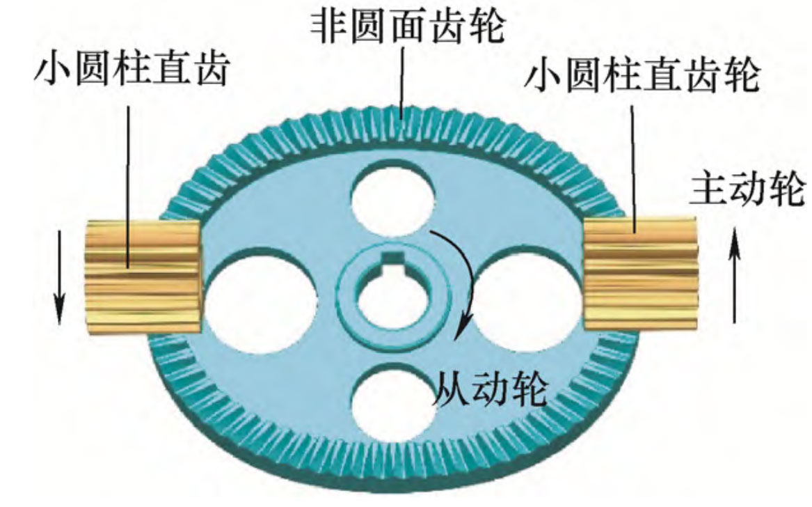
The non circular gear differential consists of a new type of spatial variable transmission ratio gear, as shown in the figure, which is a second-order non circular gear that can mesh with a standard involute gear for transmission. In general, a small cylindrical spur gear is the driving wheel, a non circular gear is the driven wheel, and the rotating shaft of the small cylindrical gear and the non circular gear intersect. Non circular gears inherit the transmission characteristics of conventional circular gears, with advantages such as no axial force, good interchangeability, and large overlap of cylindrical gears. In addition, for conventional non circular gear pairs, when one of the gears is processed, the tooth distribution and shape of the other gear are uniquely determined. Therefore, when machining the second non circular gear, it is necessary to accurately align the tool to ensure correct meshing, which poses great difficulties for the processing and replacement of non circular gears. The non circular gear mechanism shown in the figure does not require tool alignment or tooth alignment during machining and installation, as the distribution of teeth on the non circular gear does not affect its correct meshing with the cylindrical gear. This greatly reduces the difficulty of machining and replacing the gear. Due to its advantages in manufacturing, service, and maintenance processes, non circular gears are more suitable for variable transmission ratio differentials in vehicles compared to non conical gears.

In the figure, the pitch cylinder surface of the small cylindrical spur gear is tangent to the pitch surface of the non-circular gear, and a pitch curve related to the transmission ratio is distributed on the pitch surface of the non-circular gear. When the rotation axes of the two are orthogonal, the pitch surface of the non-circular gear is a plane, and the corresponding pitch curve is a plane curve. Any closed curve can be used. In this paper, the non-circular gear is orthogonal, and the formula for taking the pitch curve is:

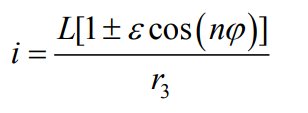
In the equation, r ϕ Are the radial and polar angles of the pitch curve of non circular gears, and L is the base circle radius of the pitch curve of non circular gears, ε Is the eccentricity of pitch curve of non-circular gear, and n is the order of non-circular gear. If a non circular gear starts to rotate at a polar angle of 0, its polar angle is equal to the rotational angle. For the convenience of description and calculation, this article believes that the rotational angle and polar angle of a non circular gear are equal, and the transmission ratio of a non circular gear can be expressed as:

In the formula, i is the ratio of rotational speed between a small cylindrical spur gear and a non circular gear, and r3 is the pitch radius of the small cylindrical spur gear.
