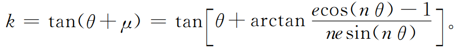
As shown in the figure 1, the tool rack pitch line AB is a straight line. During gear hobbing, AB is tangent to the pitch curve of high-order elliptical gear at point t and rolls with pure gear hobbing. Slope of AB:
The equation of tool rack pitch line (center line) AB is:
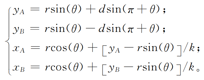
Where D is the centerline length shown in the virtual gear tooth hobbing.
In the hobbing process of several high-order elliptic gears with a = 150, n = 2,…, 4, the positional relationship between the rack pitch line and the gear pitch curve is shown in Fig. 2. All the pitch curves in Fig. 2A, FIG. 2B and Fig. 2C meet the formula, and the envelope of the rack pitch line is the gear pitch curve, which can be processed by gear hobbing; Part of the pitch curve in Figure 2D does not meet the formula. If the rack pitch line crosses the gear pitch curve, the gear will be overcut, so it cannot be rolled.

The thick line shown in Fig 3 The thick line shown in Figure 6 is a pitch tool rack, and the overall rack can be drawn in this cycle. The tool for machining helical gear rack needs to set the normal surface parameter Mn, α n. Replace h * an, c * n with end face parameter MT, α t,h*at ,c*t.
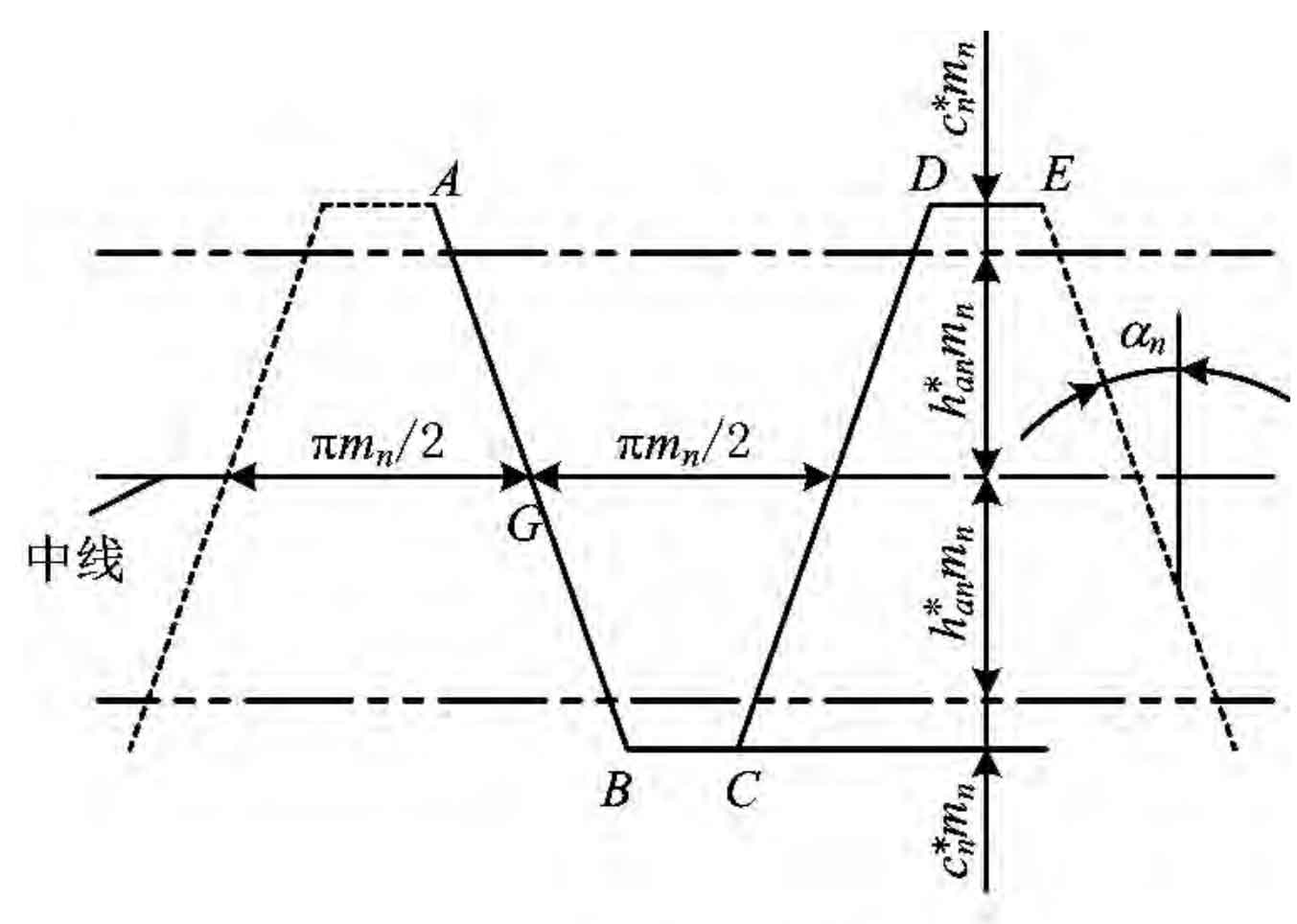
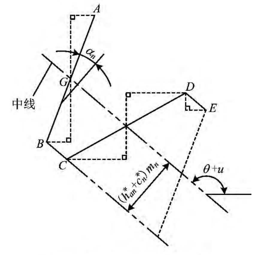
The intersection of one side edge of the rack and the center line shown in Figure 3 is g. the overall movement of the rack along the center line can be characterized by the displacement of point G relative to point t. The position control expression of rack feature points according to the relationship shown in Figure 4 is as follows:
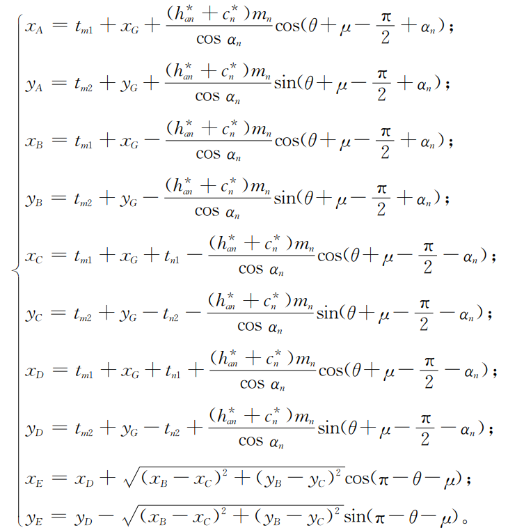
Where:
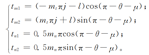
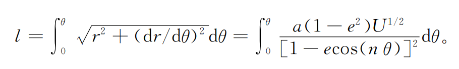
Where: J is the number of pitches of the display tool rack; L is the rack displacement TG at any time, which is equal to the pitch curve arc length at hobbed by gear hobbing, that is, the displacement of point G relative to point t: