
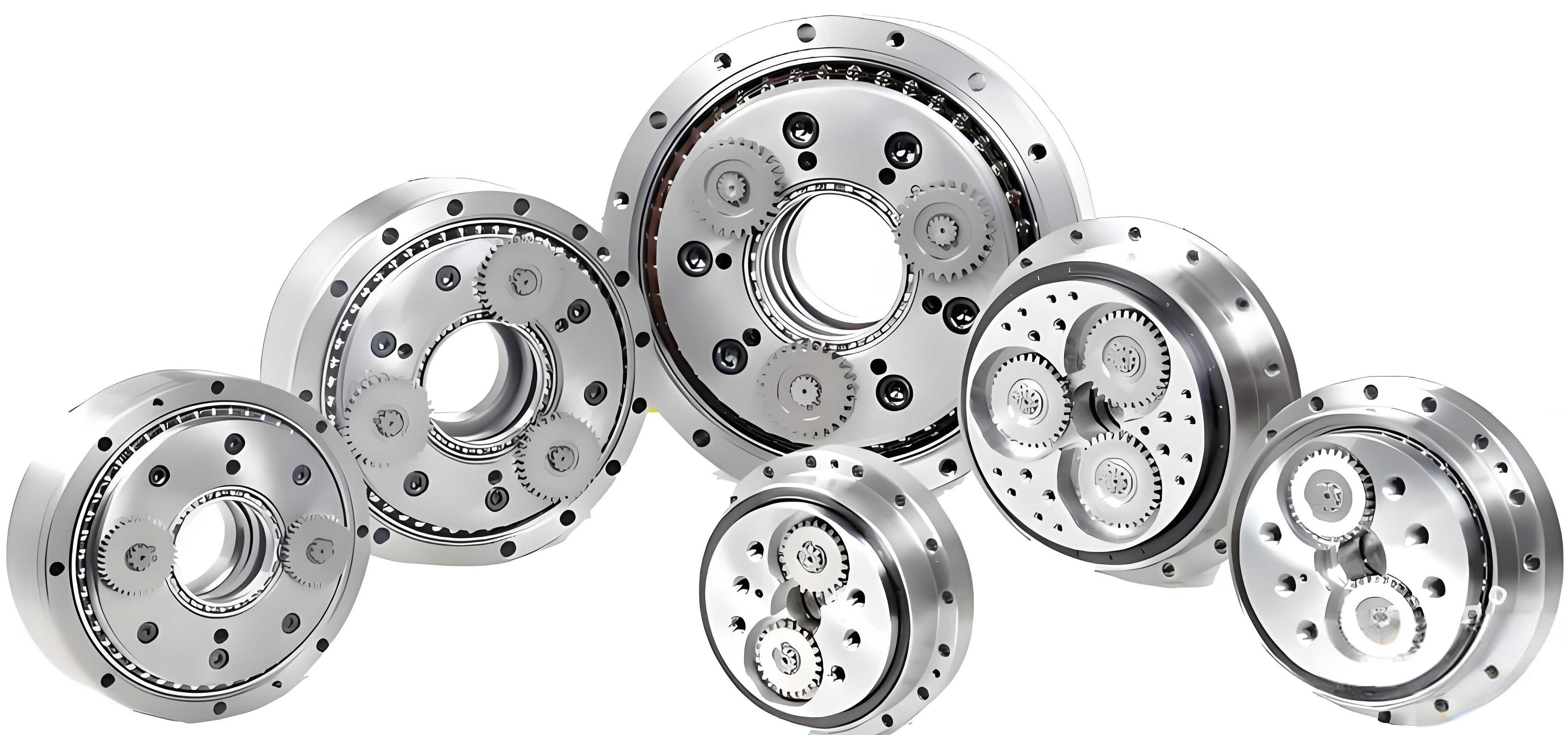
In recent years, with the continuous development of manufacturing industries globally, industrial robots have been increasingly deployed in high-risk and labor-intensive tasks across various fields. The rotary vector reducer serves as the core transmission component in the joints of industrial robots. The manufacturing of high-precision rotary vector reducers has always been a challenging aspect in robot production, with key technologies predominantly held by developed countries such as the United States, Japan, and Germany. This dependence on imported precision reducers significantly restricts the advancement of domestic manufacturing sectors, creating an urgent need to master the production techniques for these critical components. By doing so, the development of the robotics industry can proceed without being constrained by external technological monopolies. Through sensitivity analysis of transmission accuracy errors in rotary vector reducers, it has been found that the cycloid-pin gear transmission section has a substantial impact on overall precision. Consequently, the cycloid gear must exhibit high accuracy, typically requiring dimensional tolerances and geometric accuracies at levels 4 to 5 during design. This imposes stringent demands on the machining processes for the part. In this paper, I will detail the processing design for the cycloid gear component and conduct a simulation analysis on the quenching process, which induces significant deformation, to effectively guide its manufacturing. The rotary vector reducer is a pivotal element in robotic systems, and optimizing its cycloid gear production is essential for enhancing performance and reliability.
The transmission mechanism of a rotary vector reducer consists of a two-stage system: the first stage involves planetary transmission with involute gears, while the second stage comprises a cycloid-pin wheel planetary transmission. Notably, the pin gear structure in a rotary vector reducer differs from that in conventional cycloid-pin wheel planetary reducers. In standard reducers, pin gears are composed of pins and a pin gear housing, where pins provide two or three points of support on the housing. The cycloid gear meshes with the pin gear housing to drive rotational motion, allowing the housing to roll on the pins. This configuration, as illustrated in structural diagrams, reduces requirements for machining precision of the cycloid gear and pins but compromises the stiffness of the reducer. In contrast, the rotary vector reducer features pins directly installed into pin slots on the housing via transition fits, resulting in full-point support. This design enhances rigidity but demands higher machining accuracy for the cycloid gear, pins, and pin slots on the housing. Additionally, it necessitates superior strength, surface hardness, wear resistance, and anti-fatigue properties for the cycloid gear and pins. Such distinctions underscore the criticality of precision engineering in rotary vector reducers, making the cycloid gear a focal point for quality assurance.
Based on the transmission form analysis of the rotary vector reducer, I selected GCr15 as the material for the cycloid gear. Chromium in GCr15 improves heat treatment processes, enhancing hardenability, microstructural uniformity, and tempering resistance. After heat treatment, GCr15 steel achieves high and uniform hardness along with excellent wear resistance. Moreover, the processing techniques for GCr15 are well-established, making it a suitable choice for this application. The material properties of GCr15 are crucial for withstanding the operational stresses in a rotary vector reducer, and its selection is foundational to the subsequent process design.
The main challenges in machining the cycloid gear include high requirements for positional and dimensional accuracy of the central hole and bearing holes on both sides, parallelism and surface roughness of the end faces, and the precise tooth profile. Additionally, significant deformation can occur after carburizing and quenching. To address these difficulties, I have designed a comprehensive processing plan based on practical production considerations. The cycloid gear is initially formed through precision forging, leaving appropriate machining allowances for subsequent heat treatment and grinding operations. Precision forging imparts high strength and bending fatigue life to the part while ensuring efficient production. The detailed process flow is summarized in Table 1 below.
| Step | Process Name | Description |
|---|---|---|
| 1 | Precision Forging | Direct forging to near-net shape with machining allowances. |
| 2 | Isothermal Annealing | Relieve residual stresses and reduce hardness for easier machining. |
| 3 | Shot Blasting | Remove surface oxide layers from forging and annealing. |
| 4 | Carburizing and Quenching | Enhance surface hardness, wear resistance, and contact fatigue performance. |
| 5 | Tempering | Eliminate internal stresses, reduce deformation, and improve part properties. |
| 6 | Rough Grinding | Grind end faces, tooth profile surfaces, central and bearing holes coarsely. |
| 7 | Finish Grinding | Precision grind end faces, tooth profile surfaces, central and bearing holes. |
| 8 | Surface Cleaning | Clean residual iron chips and grinding fluid from the part. |
| 9 | Inspection | Verify machining accuracy through measurements. |
| 10 | Storage | Store in inventory for future assembly. |
The selection of grinding allowances significantly influences part quality and efficiency. If the allowance is less than the maximum thermal deformation, corrections become impossible, leading to part rejection. Conversely, excessive allowances reduce production efficiency and shorten grinding machine lifespan. To determine an optimal allowance, I performed a thermomechanical simulation of the quenching process on the cycloid gear, combining results with practical experience to estimate post-quench deformation. This approach is vital for the rotary vector reducer’s cycloid gear, as precise tolerances ensure smooth operation in robotic joints.
Using ANSYS software, I conducted a coupled thermal-structural simulation to analyze the quenching process, examining stress distribution and strain in the cycloid gear. This simulation provides insights into deformation patterns, aiding in allowance determination. The finite element analysis involved several steps: model creation, material property definition, meshing, load application, and result interpretation. For model building, due to ANSYS’s limitations in complex 3D modeling, I utilized SolidWorks to generate the cycloid gear’s 3D geometry based on parametric equations for the tooth profile. The model was then imported into ANSYS, as shown in conceptual representations. The tooth profile curve is derived from the cycloid equation, which for a rotary vector reducer can be expressed as:
$$ x = (R_r + R_p) \cos(\theta) – e \cos\left( \frac{R_r + R_p}{R_p} \theta \right) $$
$$ y = (R_r + R_p) \sin(\theta) – e \sin\left( \frac{R_r + R_p}{R_p} \theta \right) $$
where $R_r$ is the radius of the pin circle, $R_p$ is the radius of the cycloid gear, $e$ is the eccentricity, and $\theta$ is the rotation angle. This mathematical foundation ensures accurate gear geometry for simulation.
Material properties for GCr15 were defined according to its thermomechanical parameters, which vary with temperature. Table 2 lists key properties at different temperatures, essential for the simulation accuracy.
| Temperature (°C) | Density (kg/m³) | Poisson’s Ratio | Thermal Expansion Coefficient (10⁻⁶/°C) | Elastic Modulus (N/m²) | Specific Heat (J/(kg·K)) | Thermal Conductivity (W/(m·K)) |
|---|---|---|---|---|---|---|
| 20 | 7830 | 0.3 | 11.5 | 2.12e11 | 460 | 40.1 |
| 100 | 7830 | 0.3 | 11.9 | 2.06e11 | 494 | 38.8 |
| 300 | 7830 | 0.3 | 12.5 | 1.93e11 | 560 | 36.7 |
| 600 | 7830 | 0.3 | 13.5 | 1.68e11 | 745 | 30.1 |
| 900 | 7830 | 0.3 | 14.5 | 1.20e11 | 620 | 25.1 |
Meshing was performed using adaptive methods with local refinements at complex regions like tooth roots and hole edges to ensure result precision. The analysis type was set to transient thermal-structural coupling, accounting for temperature-dependent material behavior. For initial conditions, based on the heat treatment process for GCr15 cycloid gears, I assumed an oil quenching at 840°C with an oil bath initial temperature of 60°C, followed by tempering at 170°C to achieve optimal mechanical properties with minimal distortion. In simulation, the model’s initial temperature was set to 840°C, and the environment to 60°C. Boundary conditions involved convective heat transfer between the gear surface and quenching oil. Typically, quenching is modeled as a nonlinear convective process due to varying heat transfer coefficients with temperature. From literature, the surface heat transfer coefficient for GCr15 in quenching oil is depicted in curves, and for simplification, I approximated it as a constant value of 840 W/(m²·K) for the simulation, representing an average over the quenching period. The heat transfer during quenching can be described by Newton’s law of cooling:
$$ q = h (T_s – T_{\infty}) $$
where $q$ is the heat flux, $h$ is the heat transfer coefficient, $T_s$ is the surface temperature, and $T_{\infty}$ is the oil temperature. Integrating this into the finite element model allows predicting thermal gradients and subsequent stresses.
After solving, the simulation results revealed stress and strain distributions after one minute of quenching. The equivalent stress cloud indicated maximum thermal stresses of approximately 162.59 MPa, concentrated around the tooth profile surfaces where geometric discontinuities exist. The deformation cloud showed a maximum thermal strain of about 0.1587 mm, primarily in thin-walled sections between holes. These findings suggest that deformation is most critical in areas with reduced stiffness, necessitating careful allowance planning. The stress distribution follows the general equation for thermal stress:
$$ \sigma = E \alpha \Delta T $$
where $\sigma$ is the thermal stress, $E$ is the elastic modulus, $\alpha$ is the thermal expansion coefficient, and $\Delta T$ is the temperature difference. However, due to complex geometry and transient effects, numerical simulation like ANSYS provides more accurate insights for the rotary vector reducer’s cycloid gear.
In actual production, thermal deformation is influenced by multiple factors such as oil pressure in the quenching bath, part orientation, oil viscosity, and cooling uniformity. Observations of quenched cycloid gears showed deformations ranging from 0.10 to 0.18 mm, with some warping due to uneven contact with the oil. To minimize this, it is advisable to ensure all surfaces are adequately exposed during quenching and to arrange parts systematically in batches, avoiding random stacking. Furthermore, tempering plays a crucial role in relieving residual stresses and reducing distortion. Practical experiments demonstrated that applying pressure on the end faces during tempering, using a specially designed fixture, effectively mitigates warping. This fixture maintains flatness, aligning with the precision requirements for the rotary vector reducer. The design considerations for such fixtures include load distribution and thermal stability, which I incorporated based on simulation insights.
Comparing simulation results with actual measurements, the deformation trends are consistent, though absolute values differ slightly due to real-world complexities. This validates the simulation’s reliability for guiding allowance selection. Based on this analysis, I recommend a finish grinding allowance of 2% to 3% of part dimensions, balancing error correction and machining efficiency. This allowance ensures that post-quench distortions can be removed without excessive material removal, optimizing the production cycle for the rotary vector reducer’s cycloid gear. Future work could involve refining the thermomechanical model by incorporating more accurate boundary conditions, such as variable heat transfer coefficients or phase transformation effects, to enhance prediction accuracy. Additionally, exploring alternative materials or heat treatment methods may further reduce deformation and improve performance.
In conclusion, the processing design for the cycloid gear in a rotary vector reducer involves precision forging, careful heat treatment, and grinding operations. The thermomechanical simulation using ANSYS provides valuable data on quenching-induced deformations, informing allowance decisions and highlighting critical areas like thin walls and tooth profiles. While discrepancies exist between simulation and reality, the overall deformation patterns offer practical guidance for manufacturing. By implementing controlled quenching practices and tempering fixtures, warping can be minimized, contributing to higher quality cycloid gears. This comprehensive approach not only addresses current production challenges but also lays groundwork for advancing rotary vector reducer technology, ultimately supporting the development of more reliable and efficient industrial robots. The iterative process of design, simulation, and validation underscores the importance of integrated engineering in mastering core components like the rotary vector reducer.