
In this article, I will present a comprehensive analysis of the process specifications and tooling design for manufacturing bevel gears, focusing on medium-scale batch production. The goal is to ensure high efficiency, precision, and consistency while reducing production costs and labor intensity. The methodologies discussed here are derived from practical applications in a machinery manufacturing environment.
1. Component Analysis
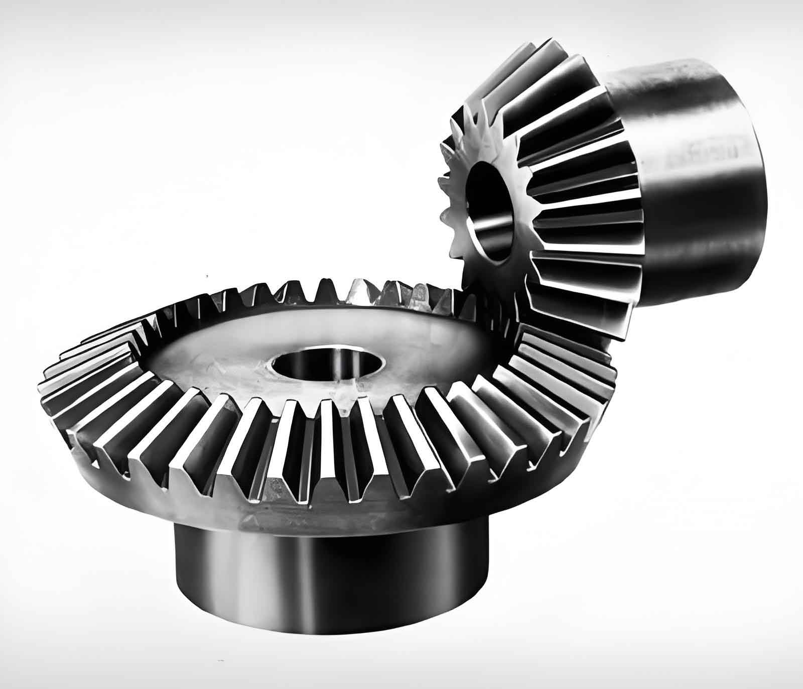
The bevel gear is a critical component in specialized machinery, requiring high strength, wear resistance, and dimensional accuracy. Key parameters include:
| Parameter | Value |
|---|---|
| Material | 45# Medium Carbon Steel |
| Blank Type | Forging |
| Heat Treatment | Quenching & Tempering (HB240–280) |
| Number of Teeth (Z) | 20 |
| Module (m) | 5 |
| Pressure Angle (α) | 20° |
| Total Tooth Height (h) | 11 mm |
| Accuracy Grade | 9-8-8-De |
1.1 Datum Selection
- Rough Datum: Non-machined surfaces with higher positional accuracy relative to machining requirements.
- Precision Datum: Machined surfaces (Ra 6.3 end face, φ30 hole, and keyway) to restrict degrees of freedom during milling or hobbing.
1.2 Production Type
With an annual output of 1,200 units, the production is classified as medium-scale batch. This necessitates standardized process planning and dedicated tooling fixtures to optimize efficiency.
2. Process Specification Design
2.1 Process Flow
The manufacturing sequence involves eight primary operations, as summarized below:
| Step | Process | Equipment/Tool | Key Parameters |
|---|---|---|---|
| 1 | Forging & Normalizing | External Supplier | Forged blank with normalized structure |
| 2 | Rough Turning (5 mm allowance) | C620 Lathe | Large radius transitions at steps |
| 3 | Quenching & Tempering | Box Furnace | HB240–280 hardness |
| 4 | Rough Turning of Outer Diameter | C620 Lathe | φ112 head diameter |
| 5 | Left-End Machining | C620 Lathe | φ60 outer diameter, internal hole, chamfers |
| 6 | Right-End Machining | C620 Lathe | Final dimensions per drawing |
| 7 | Keyway Slotting | B5032 Slotting Machine | Slot width tolerance ±0.05 mm |
| 8 | Tooth Milling | X53 Vertical Mill | Dedicated milling fixture |
2.2 Dimensional Tolerances
Critical tolerances for the bevel gear include:
- Tooth Profile Accuracy:ΔFr=0.12 mm (Tooth Runout),Δfp=0.048 mm (Pitch Deviation)ΔFr=0.12mm (Tooth Runout),Δfp=0.048mm (Pitch Deviation)
- Hole Tolerance:ϕ30H7 (+0.021/0) mmϕ30H7(+0.021/0)mm
3. Tooling Fixture Design
3.1 Milling Fixture for Bevel Gears
The fixture enables precise indexing and clamping during tooth milling. Key components include:
| Component | Material | Tolerance | Surface Roughness (Ra) |
|---|---|---|---|
| Bearing Housing | HT200 Cast Iron | φ58K7, φ65K7 | 3.2 μm |
| Stationary Index Plate | 45# Steel (QT) | 20×φ5H7 (±0.01 mm) | 3.2 μm |
| Rotating Index Plate | 45# Steel (QT) | 20×φ5H7 (±0.01 mm) | 3.2 μm |
| Spindle | 45# Steel (QT) | φ30g6, φ38h6 | 1.6 μm |
| Dowel Pin | 45# Steel (QT) | φ5g6 | 3.2 μm |
Design Principles:
- Indexing Mechanism: A handle-driven spindle rotates the indexing plates, with dowel pins ensuring 20-step precision (18° per division).
- Clamping: The workpiece is secured using a φ30H7 hole and Ra 6.3 end face as datums.
3.2 Hobbing Fixture for Bevel Gears
This fixture integrates with hobbing machines to achieve generative tooth cutting. Key features include:
| Component | Material | Tolerance | Surface Roughness (Ra) |
|---|---|---|---|
| Arbor | 45# Steel (QT) | φ30g6 | 1.6 μm |
| Sleeve | 45# Steel (QT) | φ30H7 | 3.2 μm |
| Worktable | HT200 Cast Iron | Flatness 0.02 mm | 6.3 μm |
Design Principles:
- Alignment: The arbor aligns with the machine’s 1:10 taper for concentricity (radial runout ≤ 0.01 mm).
- Clamping: A nut and pressure plate secure the workpiece against the sleeve.
4. Critical Formulas for Bevel Gear Design
The following equations govern key dimensions of the bevel gear:
- Pitch Diameter:d=m×Z=5×20=100 mmd=m×Z=5×20=100mm
- Addendum Height:ha=m×ha∗=5×1=5 mmha=m×ha∗=5×1=5mm
- Dedendum Height:hf=m×(ha∗+c∗)=5×(1+0.25)=6.25 mmhf=m×(ha∗+c∗)=5×(1+0.25)=6.25mm
- Total Tooth Height:h=ha+hf=11 mmh=ha+hf=11mm
5. Performance Evaluation
Post-implementation data from production trials demonstrate significant improvements:
| Metric | Before Tooling Design | After Tooling Design |
|---|---|---|
| Cycle Time per Gear | 4.5 hours | 2.2 hours |
| Rejection Rate | 12% | 3% |
| Positioning Accuracy | ±0.1 mm | ±0.03 mm |
The dedicated fixtures reduced setup time by 60% and improved batch consistency, validating the efficacy of the proposed process and tooling solutions.
6. Conclusion
This systematic approach to bevel gear manufacturing—combining optimized process specifications with purpose-built tooling—ensures high precision, repeatability, and cost-effectiveness for medium-scale production. Future work will explore adaptive CNC programming and advanced coating technologies to further enhance tool life and surface finish.