
I investigated a longitudinal cracking failure that appeared in a finished 22CrMoH pinion gear after the pinion gear had completed machining, carburizing, quenching, low-temperature tempering, straightening, cleaning, and either packaging or assembly preparation. In my evaluation, the crack was not associated with gross chemical nonconformity, macroscopic nonmetallic inclusions, or obvious surface decarburization. Instead, the evidence indicated that the pinion gear failed by a delayed quench crack that initiated below the V-shaped spline root and propagated longitudinally. I approached the problem as a manufacturing metallurgy and failure-analysis task: I first verified the chemical composition, then examined the macroscopic crack path, then studied the microstructure, grain size, and fracture morphology, and finally combined those findings with quenching-stress and notch-stress reasoning to explain why the pinion gear cracked.
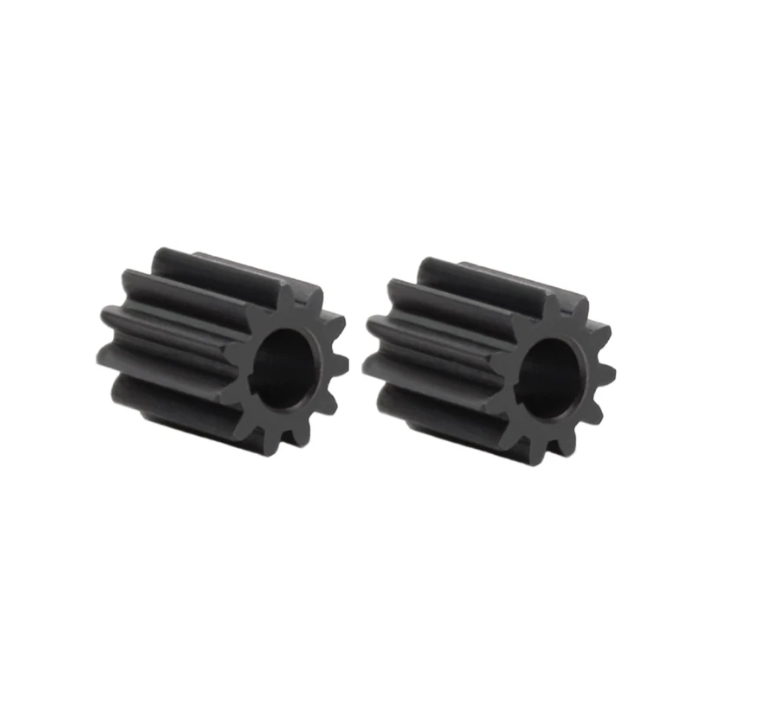
My Scope and the Failure Context
The component I examined was an active driving bevel pinion gear, referred to throughout my analysis as the pinion gear. The pinion gear is a highly loaded transmission component. In service, a pinion gear of this type must tolerate bending fatigue, contact fatigue, torsional loading, and occasional impact. For that reason, 22CrMoH steel is often selected because it can develop a hard, wear-resistant carburized case and a tough, strong core after appropriate quenching and tempering. However, the same combination of high hardenability, a carburized case, a relatively thick section, and a sharp spline-root geometry can make the pinion gear sensitive to quenching stress. When the stress state exceeds the local fracture resistance, a pinion gear can crack during quenching, during straightening, during cleaning, or even after a delay in storage. I classified the present event as a delayed quench crack, also known as delayed cracking or storage cracking, because the crack path showed no oxidation or decarburization and the fracture surface was fresh, consistent with cracking after the final thermal cycle or after tempering.
I did not treat the crack as an isolated defect. I treated it as the end point of a chain of thermal, microstructural, geometric, and residual-stress events. For a pinion gear, the most important part of that chain is often the transition between the carburized case and the core. That transition can contain a sharp gradient in carbon content, hardness, yield strength, and transformation behavior. When the pinion gear is quenched, the case and core attempt to transform at different times and with different volume changes. The spline root acts as a stress concentrator. If the quenching intensity is too high, or if the tempering treatment is insufficient to relax residual stress, the pinion gear may remain in a meta-stable stress state until a small additional stimulus causes delayed cracking. My analysis focused on that possibility.
Manufacturing Route of the Pinion Gear
I reconstructed the manufacturing route of the pinion gear from the process information associated with the failed component. The route began with bar stock, followed by hot forging, normalizing, machining, carburizing and quenching, cleaning, low-temperature tempering, and straightening. Each step can influence the final stress state of the pinion gear. Forging can introduce flow-line orientation and local residual strain. Normalizing can refine and homogenize the microstructure. Machining creates the spline geometry and the surface finish of the pinion gear. Carburizing establishes the carbon profile. Quenching generates the case-core hardness difference. Tempering reduces brittleness and residual stress. Straightening can add additional plastic strain and residual stress. I summarized the route and its possible contribution in Table 1.
| Process Step | Typical Parameter I Used for Assessment | Influence on the Pinion Gear |
|---|---|---|
| Bar cutting | Cut-to-length stock | Establishes initial billet mass and forging volume for the pinion gear |
| Hot forging | \(1200 \pm 20^\circ C\) | Forms the pinion gear blank and introduces local flow lines and residual strain |
| Normalizing | \(940^\circ C\) | Refines prior-austenite grain structure and improves machinability of the pinion gear |
| Machining | Spline and gear tooth cutting | Creates the V-shaped spline root and other stress concentrations in the pinion gear |
| Carburizing and quenching | \(920\!-\!930^\circ C\), carbon potential \(1.1\!-\!1.2\), oil at \(60^\circ C\) | Produces the case-core carbon profile and the main quenching stress in the pinion gear |
| Cleaning | \(70\!-\!100^\circ C\) | Removes quenching oil and residue from the pinion gear surface |
| Low-temperature tempering | \(180\!-\!200^\circ C\) | Relaxes part of the quenching stress and tempers martensite in the pinion gear |
| Straightening | Mechanical correction | Can add residual stress and local plastic strain to the pinion gear |
I considered the carburizing and quenching step to be the most probable origin of the stress state that led to cracking, but I did not ignore the possibility that straightening after tempering contributed to the final failure. For a pinion gear, straightening is a common operation because distortion after quenching can exceed the allowable runout or tooth alignment tolerance. However, straightening a hardened pinion gear can impose tensile stress on the surface or near-surface region. If the pinion gear already contains a high tensile residual stress below the spline root, straightening may trigger the last increment of crack extension. I therefore kept both quenching and post-quenching operations in my causal model.
Inspection Program I Used
I used a multi-scale inspection program. I first performed chemical analysis by optical emission spectrometry. I then examined the failed pinion gear visually and with low-magnification photography. I sectioned the cracked region, prepared metallographic specimens, and examined the crack path and base microstructure. I measured grain size after suitable etching. I examined the fracture surface by scanning electron microscopy. I also used the measured chemical composition and process parameters to estimate hardenability, transformation stress, and notch stress. Table 2 summarizes the inspection program and the purpose of each method.
| Inspection Method | Specimen or Location | Information I Wanted |
|---|---|---|
| Optical emission spectrometry | Sample from the pinion gear | Verify C, Si, Mn, Cr, Mo, P, S, and Al against 22CrMoH requirements |
| Macroscopic visual inspection | Outer surface and spline region | Measure crack length, opening, orientation, and relation to the pinion gear spline |
| Sectioning and macro-etching | Transverse and longitudinal sections | Determine crack depth, path, branching, and relation to the case-core transition |
| Optical microscopy | Crack vicinity and center core | Identify martensite, retained austenite, carbides, and oxidation or decarburization |
| Grain-size measurement | Case and core regions | Assess prior-austenite grain coarsening and its effect on toughness |
| Scanning electron microscopy | Fracture origin and propagation region | Classify fracture mode and locate nonmetallic inclusions or defects |
| Analytical stress estimation | Geometry and process data | Estimate thermal, transformation, and notch stresses in the pinion gear |
Chemical Composition Verification
I verified the chemical composition of the pinion gear because a simple chemistry error can change hardenability, case depth, and cracking susceptibility. The measured values were consistent with the specification for 22CrMoH steel. Carbon, manganese, chromium, and molybdenum were all within the expected range. Phosphorus and sulfur were low. Aluminum was also within the required limit. The measured composition is given in Table 3. I did not find a chemistry deviation that could by itself explain the crack in the pinion gear.
| Element | Specification Range, wt.% | Measured Value, wt.% | My Assessment for the Pinion Gear |
|---|---|---|---|
| C | 0.19–0.25 | 0.21 | Within range; suitable for carburizing |
| Si | 0.17–0.37 | 0.30 | Within range; no unusual effect |
| Mn | 0.60–1.00 | 0.90 | Within range; increases hardenability |
| Cr | 0.90–1.25 | 1.18 | Within range; improves case hardenability |
| Mo | 0.35–0.45 | 0.37 | Within range; suppresses temper embrittlement |
| P | \(\le 0.015\) | 0.011 | Low; no strong grain-boundary embrittlement risk |
| S | \(\le 0.025\) | 0.005 | Low; no significant sulfide inclusion risk |
| Al | \(\le 0.03\) | 0.023 | Within range; fine-grain control is expected |
I also calculated a simple carbon equivalent to compare the base hardenability of the pinion gear with the expected 22CrMoH behavior. The carbon equivalent can be estimated as:
$$C_{eq}=C+\frac{Mn}{6}+\frac{Cr+Mo+V}{5}+\frac{Ni+Cu}{15}$$
Using the measured values and neglecting V, Ni, and Cu because they were not reported in the relevant specification range, I obtained:
$$C_{eq}=0.21+\frac{0.90}{6}+\frac{1.18+0.37}{5}$$
$$C_{eq}=0.21+0.15+0.31=0.67$$
This value is consistent with a medium-carbon, high-hardenability carburizing steel. For the pinion gear, such a composition means that even the core can transform to martensite during oil quenching, especially in thicker sections. A martensitic core is desirable for strength, but it also increases the volume change and the transformation stress during quenching. I therefore considered the core transformation behavior to be part of the cracking problem, not merely a background property.
Macroscopic Features of the Pinion Gear Crack
Macroscopically, I observed a longitudinal crack on the pinion gear surface. The crack was approximately 16 cm long. It was relatively straight and followed the axial direction of the pinion gear. The largest opening was at the spline root, where the crack mouth opened to approximately 0.5 mm. After sectioning, I measured the maximum crack depth as approximately 12.6 mm. The crack did not follow the tooth flank in a random manner; instead, it was associated with the V-shaped spline root. This location is critical because a spline root acts as a geometric notch in the pinion gear. Table 4 summarizes the macroscopic crack measurements I made.
| Macroscopic Feature | Measurement or Observation | Interpretation for the Pinion Gear |
|---|---|---|
| Crack orientation | Longitudinal | Consistent with axial stress and spline-root stress concentration |
| Crack length | Approximately 16 cm | Long crack path requiring a sustained driving stress |
| Maximum opening | Approximately 0.5 mm at spline root | Indicates high tensile stress at the root of the pinion gear |
| Maximum depth | Approximately 12.6 mm | Extends well below the carburized case into the core transition |
| Crack path | Relatively straight, then irregular near tip | Mixed stress-controlled and microstructural influence |
| Location | V-shaped spline root | Notch effect is a major contributor in the pinion gear |
I paid particular attention to whether the crack was open at the surface or whether it initiated internally and later reached the surface. The crack mouth at the spline root was wide, but the crack path was narrower at the extreme tip. The crack was not filled with oxide scale. I did not observe decarburization or carburization along the crack flanks. These observations are important because they distinguish a quench crack from a forging crack, a rolling crack, or a heat-treatment crack that formed at high temperature in an oxidizing atmosphere. If the crack had formed before or during carburizing, I would expect oxidation, decarburization, or internal scale along the crack. If the crack had formed during forging, I would expect scale, decarburization, or a different morphology. Because the crack was clean, I concluded that it formed after the pinion gear had already developed its final or near-final microstructure.
Fracture Origin and Crack Path
From the fracture surface and the sectioned specimen, I determined that the crack origin was located about 2–3 mm below the surface of the V-shaped spline root. This position is not random. It lies near the transition between the carburized case and the core of the pinion gear. In a carburized pinion gear, the case has a higher carbon content, a higher hardness, and a lower martensite-start temperature than the core. During quenching, the case may transform first or last depending on the carbon profile and cooling rate. At the same time, the thermal contraction of the surface and the core differs. The result is a complex residual stress field. The transition zone often contains a tensile stress peak because the hard case resists plastic flow while the core transforms and expands. I represented the local stress state in a simplified manner as:
$$\sigma_{res}(z)=\sigma_{thermal}(z)+\sigma_{transformation}(z)+\sigma_{notch}(z)$$
where \(z\) is the depth below the spline root surface, \(\sigma_{thermal}\) is the thermal stress from differential cooling, \(\sigma_{transformation}\) is the stress from martensitic transformation and volume change, and \(\sigma_{notch}\) is the stress concentration caused by the V-shaped spline root. When the sum of these stresses exceeds the local fracture strength, a crack can initiate in the pinion gear. The location 2–3 mm below the surface is consistent with a maximum in the tensile residual stress field rather than with a purely surface-initiated fatigue crack.
The crack path also provided information. The crack propagated longitudinally and then branched in some areas. The crack tip was sharp, and the crack followed prior-austenite grain boundaries in some regions. This intergranular component can occur when the local stress is high, when the grain boundaries are weakened, or when hydrogen is present. I did not find strong evidence of hydrogen embrittlement, but delayed cracking after quenching is often assisted by hydrogen that remains in the steel after heat treatment. For the pinion gear, the combination of a sharp notch, a susceptible transition zone, and a high residual tensile stress is sufficient to explain delayed cracking even without a large hydrogen concentration. The stress intensity at the crack tip can be approximated by:
$$K_I=Y\sigma\sqrt{\pi a}$$
where \(K_I\) is the mode I stress intensity factor, \(Y\) is a geometry factor for the pinion gear spline root, \(\sigma\) is the local tensile stress, and \(a\) is the crack depth. As the crack extends, \(K_I\) increases if the stress field remains tensile. This explains why a small initial crack below the spline root can grow into a long longitudinal crack in the pinion gear.
Microstructure and Grain Size
I examined the microstructure near the crack and in the center of the pinion gear. Both regions consisted of quenched and low-temperature-tempered martensite. I did not find abnormal ferrite, bainite, or massive carbide networks that would indicate a gross heat-treatment error. The prior-austenite grain size was approximately 6.5 ASTM in both the near-crack region and the core. This grain size is not exceptionally coarse, but it is not ultrafine. For a pinion gear, a finer prior-austenite grain size would improve toughness and reduce crack sensitivity. I therefore considered grain size as a secondary factor that may have contributed to the crack resistance rather than as the primary cause. Table 5 summarizes the microstructural observations.
| Region | Microstructure | Prior-Austenite Grain Size | My Interpretation |
|---|---|---|---|
| Near crack at spline root | Quenched and low-temperature-tempered martensite | Approximately 6.5 ASTM | No oxidation or decarburization; crack formed after heat treatment |
| Center core of pinion gear | Quenched and low-temperature-tempered martensite | Approximately 6.5 ASTM | Core hardenability is high; transformation stress is significant |
| Case region | High-carbon tempered martensite with fine carbides | Approximately 6.5 ASTM | Case-core transition is the likely stress peak |
| Crack flanks | No visible scale or decarburization | Not applicable | Crack is a cold or delayed crack, not a high-temperature crack |
I also considered the effect of carbon profile on the local transformation behavior. The carbon concentration in the case of the pinion gear can be approximated by a diffusion solution:
$$C(x,t)=C_s-(C_s-C_0)\operatorname{erf}\left(\frac{x}{2\sqrt{Dt}}\right)$$
where \(C_s\) is the surface carbon potential, \(C_0\) is the initial carbon content, \(D\) is the diffusion coefficient, \(x\) is depth, and \(t\) is carburizing time. For the pinion gear, the carbon potential was reported in the range of 1.1–1.2. This high surface carbon potential can produce a case with high hardness and high retained austenite near the surface. It can also create a steep carbon gradient at the case-core transition. A steep gradient increases the difference in transformation strain between the case and core. I did not measure the exact carbon profile, but the observed crack location is consistent with the transition region where the carbon gradient and the transformation stress are both high.
Scanning Electron Microscopy of the Pinion Gear Fracture
I examined the crack origin by scanning electron microscopy. The origin was located about 2–3 mm below the surface of the pinion gear spline root. The fracture surface near the origin was relatively flat and showed cleavage-like features. The crack propagated in a radial pattern from the origin. I did not find large nonmetallic inclusions, porosity, or forging defects at the origin. The absence of a clear inclusion initiation site is significant because it means the crack was not caused by a single gross metallurgical defect. Instead, the crack initiated from the combined action of stress and microstructure. Table 6 summarizes the scanning electron microscopy findings.
| SEM Observation | Result for the Pinion Gear | Failure-Analysis Meaning |
|---|---|---|
| Origin depth | Approximately 2–3 mm below spline root surface | Coincides with case-core transition and residual stress peak |
| Fracture surface near origin | Relatively flat with cleavage features | Consistent with high-stress brittle fracture |
| Propagation pattern | Radial from origin | Indicates a single initiation site and rapid crack growth |
| Inclusions | No significant nonmetallic inclusions found | Rules out gross inclusion-initiated fracture |
| Oxidation | No oxidation on fracture surface | Supports post-tempering or delayed cracking |
| Branching | Some branching near the tip | Indicates a complex local stress state in the pinion gear |
The cleavage-like appearance does not mean that the pinion gear was necessarily brittle in service. It means that under the local stress state and strain rate, the material fractured with limited plastic deformation. In a quenched and tempered pinion gear, the case and transition zone can behave in a brittle manner if the local strength is high and the tempering treatment has not sufficiently relaxed residual stress. The scanning electron microscopy evidence therefore supported my interpretation that the crack was a quench-induced or delayed quench crack rather than a fatigue crack. A fatigue crack would usually show striations, ratchet marks, or a smoother surface after many cycles. A stress-corrosion crack might show corrosion products. I did not observe those features.
Why the Spline Root Matters in the Pinion Gear
The V-shaped spline root is one of the most important geometric features in the pinion gear. It is a notch. A notch raises the local stress above the nominal stress. For an elastic stress concentration, the maximum stress can be written as:
$$\sigma_{max}=K_t\sigma_{nom}$$
where \(K_t\) is the elastic stress concentration factor and \(\sigma_{nom}\) is the nominal stress. For a sharp V-shaped spline root, \(K_t\) can be significantly greater than 1. When the pinion gear is quenched, the nominal stress is already high because of thermal gradients and transformation strains. The notch then amplifies that stress. In addition, the spline root may have a small fillet radius, machining marks, or grinding marks that further increase the local stress. For the pinion gear, I considered the notch effect to be a multiplier on the quenching stress, not the sole cause. The crack initiated 2–3 mm below the surface rather than exactly at the surface, which suggests that the maximum stress was not at the geometric surface but slightly below it. This is typical of a carburized case-core transition, where the surface is in compression and the subsurface transition is in tension.
I also considered the stress state around the spline root in terms of axial, hoop, and radial components. In a simplified cylindrical or prismatic approximation, the residual stress can be decomposed as:
$$\sigma_{ij}=
\begin{bmatrix}
\sigma_{rr} & \tau_{r\theta} & \tau_{rz}\\
\tau_{\theta r} & \sigma_{\theta\theta} & \tau_{\theta z}\\
\tau_{zr} & \tau_{z\theta} & \sigma_{zz}
\end{bmatrix}$$
For the longitudinal crack observed in the pinion gear, the axial stress \(\sigma_{zz}\) and the hoop stress \(\sigma_{\theta\theta}\) are the most relevant. A longitudinal crack usually indicates that the hoop stress or a transverse tensile stress has exceeded the local strength. If the crack runs along the axial direction, it may open against the hoop stress. If the crack runs along the spline root, the axial stress and the notch constraint interact. I did not have full residual-stress measurements, but the crack orientation and opening were consistent with a tensile hoop or transverse stress at the spline root of the pinion gear.
Thermal and Transformation Stress in the Pinion Gear
I used a simple analytical model to estimate the thermal stress generated during quenching of the pinion gear. The thermal stress from a temperature difference can be approximated as:
$$\sigma_{th}=\frac{E\alpha}{1-\nu}\Delta T$$
where \(E\) is Young’s modulus, \(\alpha\) is the coefficient of thermal expansion, \(\nu\) is Poisson’s ratio, and \(\Delta T\) is the temperature difference between the surface and the core or between the austenitizing temperature and the oil temperature. For steel, \(E\) is approximately \(210\,\text{GPa}\), \(\alpha\) is approximately \(12\times10^{-6}\,\text{K}^{-1}\), and \(\nu\) is approximately \(0.3\). If I take a representative temperature difference during quenching, the thermal stress can be on the order of hundreds of megapascals. This is already comparable to the yield strength of the hot austenite or the freshly formed martensite. The pinion gear geometry further concentrates the stress at the spline root.
The transformation stress is even more important in a carburized pinion gear. Martensitic transformation involves a volume expansion. The transformation strain can be written as:
$$\varepsilon_{tr}=\frac{\Delta V}{3V}$$
where \(\Delta V/V\) is the relative volume change. For a high-carbon case, the volume change is larger than for a low-carbon core. If the case and core transform at different times, the mismatch produces internal stress. A simplified expression for the transformation-induced stress is:
$$\sigma_{tr}=\frac{E}{1-\nu}\left(\varepsilon_{tr,case}-\varepsilon_{tr,core}\right)$$
This equation is approximate because it ignores creep, plasticity, and the gradual nature of the transformation. Nevertheless, it shows why the case-core transition of the pinion gear is so critical. The larger transformation strain in the case, combined with the later transformation of the core, can place the transition zone in tension. The notch at the spline root then raises that tension. The result is a subsurface crack origin, exactly as I observed in the pinion gear.
Cooling Rate and Quenching Intensity
I also considered the quenching intensity. The pinion gear was quenched in oil at approximately \(60^\circ C\). The cooling rate can be approximated by:
$$\dot{T}=\frac{T_{austenitizing}-T_{oil}}{t_{cool}}$$
where \(t_{cool}\) is the characteristic cooling time. If the oil concentration, agitation, or oil temperature is not controlled, the cooling rate can vary from batch to batch. A higher cooling rate increases the thermal gradient and the transformation stress. It also increases the likelihood of cracking in a pinion gear with a sharp spline root. A lower cooling rate may reduce cracking risk, but it can also reduce case hardness and case depth if the cooling rate falls below the critical value. Therefore, the quenching process must be optimized, not simply slowed down or speeded up. I summarized the trade-off in Table 7.
| Quenching Variable | Effect on the Pinion Gear | Risk if Too High | Risk if Too Low |
|---|---|---|---|
| Oil concentration | Controls heat-transfer coefficient and cooling rate | High thermal stress and quench cracking | Insufficient case hardness and shallow case depth |
| Oil temperature | Changes viscosity and cooling curve | Nonuniform cooling and distortion | Poor quenching and soft spots |
| Agitation | Reduces vapor blanket and improves uniformity | High local cooling rate at spline root | Vapor blanket and soft patches |
| Loading arrangement | Controls heat extraction from the pinion gear | Uneven cooling and residual stress | Incomplete transformation |
| Quench delay | Time between austenitizing and quench | Temperature loss and incomplete austenitization | Not applicable |
I concluded that the quenching process for the pinion gear should be evaluated with cooling-curve measurements, not only with hardness and case-depth checks. The cooling curve at the spline root is more relevant to cracking than the cooling curve at the center of a test coupon. A pinion gear has a complex shape, and the spline root can cool differently from the tooth tip or the shank. If the spline root cools too quickly while the core is still hot, the thermal and transformation stresses can peak at the case-core transition.
Tempering and Delayed Cracking
I considered the low-temperature tempering treatment to be a critical control point for the pinion gear. Tempering at \(180\!-\!200^\circ C\) can reduce residual stress and improve toughness, but it may not fully relax the quenching stress. The amount of stress relief depends on temperature, time, and microstructure. A common approximation for tempering stress relaxation is:
$$\sigma(t)=\sigma_0\exp\left(-\frac{t}{\tau}\right)$$
where \(\sigma_0\) is the initial residual stress, \(t\) is tempering time, and \(\tau\) is a relaxation time constant that decreases with increasing temperature. For a low-temperature tempering treatment, \(\tau\) is relatively long. Therefore, a short tempering time may leave a significant fraction of the quenching stress in the pinion gear. If the pinion gear is then straightened or placed in storage, delayed cracking can occur. The crack path I observed had no oxidation, which is consistent with cracking after tempering. However, the exact timing of the crack could have been after tempering, during straightening, or during storage. I used the term delayed quench cracking because the crack was clearly linked to the quenching stress state and appeared after the main heat-treatment cycle.
I also considered the possibility of hydrogen-assisted delayed cracking. Hydrogen can enter the pinion gear during carburizing or pickling and can remain in the steel after quenching. Hydrogen diffuses to high-stress regions, such as the spline-root transition zone, and can reduce the local cohesive strength. The result is a delayed crack that forms hours or days after heat treatment. I did not perform hydrogen measurements, but the failure mode is consistent with a combination of high residual stress and a small amount of hydrogen. For the pinion gear, the most practical control measures are to reduce residual stress by optimizing quenching and tempering, and to ensure that any hydrogen introduced during processing is removed by adequate tempering or baking when necessary.
Straightening as a Secondary Contributor
I did not ignore straightening. The pinion gear may be straightened after quenching and tempering to correct distortion. Straightening introduces plastic deformation. The outer fibers of the pinion gear may be stretched or compressed, depending on the direction of bending. If the spline root is already in a tensile residual stress state, straightening can increase the local tensile stress and trigger a crack. A simple estimate of the bending stress during straightening is:
$$\sigma_b=\frac{M c}{I}$$
where \(M\) is the bending moment, \(c\) is the distance from the neutral axis, and \(I\) is the second moment of area. For a pinion gear with a complex cross-section, the stress distribution is not uniform, and the spline root can experience a local stress concentration. If the straightening force is applied through the gear teeth or spline, the local contact stress can also be high. I therefore recommended that straightening be controlled through load monitoring, temperature control if warm straightening is used, and post-straightening stress relief if the pinion gear geometry permits.
My Root-Cause Assessment
Based on the chemical composition, macroscopic crack morphology, microscopic examination, grain size, and scanning electron microscopy, I concluded that the pinion gear cracked by a quench-induced mechanism. The crack originated about 2–3 mm below the V-shaped spline root surface, at the case-core transition. The crack flanks showed no oxidation or decarburization, so the crack formed after the high-temperature carburizing stage. The absence of large inclusions or porosity ruled out a gross steel-cleanliness defect. The crack path, sharp tip, branching, and cleavage-like fracture surface were consistent with a high-stress, low-ductility fracture. The most probable sequence was: carburizing produced a high-carbon case; quenching produced a hard case and a martensitic core; the case-core transition developed a tensile residual stress peak; the V-shaped spline root amplified that stress; tempering and straightening did not fully relieve the stress; and a delayed crack initiated and propagated longitudinally in the pinion gear.
I ranked the contributing factors as follows. The primary factor was the residual stress state created by quenching, especially at the case-core transition of the pinion gear. The secondary factor was the spline-root notch geometry, which concentrated stress. The third factor was the tempering and straightening practice, which may not have provided sufficient stress relief. The fourth factor was the prior-austenite grain size, which was acceptable but not optimal for maximum toughness. The fifth factor was the possibility of hydrogen remaining in the pinion gear after processing. The chemical composition and nonmetallic inclusion content were not primary factors. Table 8 presents my root-cause ranking and the evidence for each factor.
| Rank | Contributing Factor | Evidence from the Pinion Gear | My Confidence |
|---|---|---|---|
| 1 | Quenching residual stress at case-core transition | Crack origin 2–3 mm below spline root; no oxidation; case-core mismatch | High |
| 2 | V-shaped spline-root notch | Maximum crack opening at spline root; longitudinal orientation | High |
| 3 | Insufficient tempering or stress relief | Delayed cracking after heat treatment; low tempering temperature | Medium to high |
| 4 | Straightening-induced stress | Post-quench straightening is part of the process route | Medium |
| 5 | Prior-austenite grain size | Approximately 6.5 ASTM; not coarse but not ultrafine | Medium |
| 6 | Hydrogen-assisted delayed cracking | No direct measurement; delayed nature is consistent | Low to medium |
| 7 | Chemical composition or inclusions | Composition within specification; no large inclusions found | Very low |
Stress-State Calculations and Their Meaning for the Pinion Gear
To make the failure analysis more quantitative, I combined the thermal, transformation, and notch stress estimates. I did not have a full finite-element model, but I used a simplified superposition to estimate the local stress at the crack origin. The total local stress can be written as:
$$\sigma_{total}=\sigma_{thermal}+\sigma_{transformation}+K_t\sigma_{applied}$$
For the pinion gear, the applied stress during quenching is mainly the result of thermal contraction and transformation. If I assume that the thermal stress is approximately \(300\,\text{MPa}\), the transformation stress is approximately \(400\,\text{MPa}\), and the notch factor is \(K_t=2.0\) acting on an applied or residual stress of \(150\,\text{MPa}\), then:
$$\sigma_{total}=300+400+2.0(150)=1000\,\text{MPa}$$
This is a rough estimate, but it shows that the local stress at the spline root of the pinion gear can easily approach or exceed \(1000\,\text{MPa}\). The yield strength of quenched martensite can be high, but the local fracture strength in the transition zone may be lower because of the carbon gradient, retained austenite, and high residual stress. If the local stress exceeds the local strength, a crack initiates. The stress intensity factor then determines whether the crack propagates:
$$K_I=Y\sigma\sqrt{\pi a}$$
If I take \(Y=1.1\), \(\sigma=1000\,\text{MPa}\), and \(a=2\,\text{mm}\), then:
$$K_I=1.1(1000)\sqrt{\pi(0.002)}$$
$$K_I=1.1(1000)(0.0793)=87\,\text{MPa}\sqrt{\text{m}}$$
This value is high and would be sufficient to propagate a crack in many high-strength steels if the fracture toughness is low. In a carburized case, the fracture toughness can be lower than in the core. Therefore, a small crack at the case-core transition can become unstable. This calculation supported my conclusion that the pinion gear failed by a stress-controlled, quench-related mechanism rather than by a gradual fatigue process.
Parametric Sensitivity of the Pinion Gear Process
I also evaluated how changes in process parameters would affect cracking risk. The most important variables are quenching cooling rate, oil concentration, tempering temperature, tempering time, surface carbon potential, and spline-root geometry. I summarized the sensitivity in Table 9. The table is qualitative but useful for corrective action planning. A reduction in cracking risk usually requires a reduction in the local tensile stress or an increase in the local fracture resistance. For the pinion gear, the most practical lever is to reduce the quenching cooling rate without losing the required case hardness, and to increase tempering temperature and time within the allowable hardness range.
| Parameter | Change | Effect on Residual Stress in the Pinion Gear | Effect on Cracking Risk |
|---|---|---|---|
| Quench cooling rate | Increase | Higher thermal and transformation stress | Increase |
| Quench cooling rate | Decrease | Lower stress but possible incomplete hardening | Decrease if hardness is maintained |
| Oil concentration | Increase | Slower cooling, more uniform heat transfer | Decrease |
| Oil temperature | Increase moderately | Lower thermal gradient | Decrease if still within quench window |
| Tempering temperature | Increase | More stress relaxation | Decrease |
| Tempering time | Increase | More complete stress relaxation | Decrease |
| Surface carbon potential | Decrease slightly | Lower case carbon and lower transformation mismatch | Decrease, but case hardness must still meet specification |
| Spline-root radius | Increase | Lower stress concentration | Decrease |
| Straightening load | Decrease | Less plastic strain and residual stress | Decrease |
Corrective Actions I Recommend for the Pinion Gear
I recommended a combination of process changes rather than a single change. The first action should be to increase the quench oil concentration and improve agitation uniformity, so that the pinion gear cools more slowly and evenly while still achieving the required case hardness and case depth. The second action should be to increase tempering temperature and time, within the limits allowed by the final hardness specification, to relax residual stress in the pinion gear. The third action should be to review the spline-root geometry and machining quality, especially the root radius and surface finish, because a sharper root increases stress concentration. The fourth action should be to control straightening more tightly and, if possible, perform a post-straightening stress-relief treatment. The fifth action should be to verify the carburizing carbon profile and avoid an excessively steep carbon gradient at the case-core transition. The sixth action should be to monitor hydrogen sources and include a baking or tempering step if hydrogen pickup is possible. Table 10 presents my recommended corrective actions and the expected mechanism of improvement.
| Corrective Action | Target Variable | Expected Effect on the Pinion Gear | Verification Method |
|---|---|---|---|
| Increase quench oil concentration | Cooling rate | Lower thermal and transformation stress | Cooling-curve measurement and hardness survey |
| Improve agitation uniformity | Heat-transfer uniformity | Reduce local stress peaks at spline root | Thermal mapping and distortion measurement |
| Increase tempering temperature | Residual stress and toughness | More stress relaxation in the pinion gear | Hardness, X-ray residual stress, and metallography |
| Increase tempering time | Stress relaxation | Lower delayed cracking risk | Hardness and residual-stress measurement |
| Optimize spline-root radius | Stress concentration factor | Lower local stress at the pinion gear root | Geometry inspection and finite-element analysis |
| Control straightening load | Plastic strain | Reduce secondary residual stress | Load monitoring and runout measurement |
| Review carbon potential | Case-core carbon gradient | Reduce transformation mismatch | Carbon profile analysis and case-depth measurement |
| Add hydrogen bake if needed | Diffusible hydrogen | Lower delayed cracking sensitivity | Hydrogen measurement and delayed-crack testing |
Validation Plan for the Pinion Gear
I proposed a validation plan to confirm that the corrective actions actually reduce cracking risk. The plan should include a baseline group and a modified group. The baseline group should use the original process, and the modified group should use the improved quench and temper parameters. Both groups should be evaluated for case depth, surface hardness, core hardness, microstructure, grain size, retained austenite, residual stress, distortion, and cracking incidence. The most important validation test is a delayed-crack test, because the failure in the pinion gear appeared after a delay. I recommended holding the pinion gear for at least 48–72 hours after tempering and straightening before final inspection, and then performing magnetic particle inspection or dye penetrant inspection on the spline root. Table 11 summarizes the validation plan.
| Validation Item | Baseline Group | Modified Group | Acceptance Criterion |
|---|---|---|---|
| Case depth | Original process | Optimized quench and temper | Within drawing specification |
| Surface hardness | Original process | Optimized process | Meets pinion gear hardness requirement |
| Core hardness | Original process | Optimized process | Meets strength and toughness requirement |
| Microstructure | Original process | Optimized process | Acceptable martensite and carbide morphology |
| Grain size | Original process | Optimized process | Finer than or equal to baseline |
| Residual stress | Original process | Optimized process | Lower tensile stress at spline root |
| Distortion | Original process | Optimized process | Within runout and alignment limits |
| Delayed cracking | Original process | Optimized process | No cracks after 72 hours |
Additional Discussion of the Pinion Gear Failure Mechanism
I considered whether the crack could have been caused by forging or raw material. A forging crack would usually be associated with oxide scale, decarburization, or an irregular surface. The crack I examined was clean and subsurface. A raw-material crack or seam would usually run longitudinally and could appear after machining, but it would normally show decarburization or scale if it existed before heat treatment. I did not observe those features. A grinding crack would usually be fine and shallow and would be associated with temper burn or untempered martensite. The crack in the pinion gear was deep and extended well beyond the surface. A fatigue crack would usually initiate at a stress concentration, but it would typically show beach marks or striations and would require cyclic loading. The pinion gear failed before or during assembly, so service fatigue was not the cause. Therefore, the most consistent mechanism was quenching or delayed quench cracking.
I also considered the role of retained austenite. A carburized case can contain retained austenite, especially when the surface carbon is high. Retained austenite can transform to martensite under stress or at low temperature. This transformation produces a volume expansion and can add local stress. If retained austenite is present in the case or transition zone of the pinion gear, it can contribute to delayed cracking. I did not measure retained austenite quantitatively, but the high carbon potential used in carburizing could have produced a significant amount. I therefore recommended that retained austenite be measured in future inspections and controlled through carbon potential and tempering. A lower surface carbon potential and adequate tempering can reduce retained austenite and improve dimensional stability of the pinion gear.
I also considered the effect of the case-core transition on crack arrest. In an ideal carburized pinion gear, the case is hard and wear resistant, while the core is tough and strong. The transition should be gradual enough to avoid a sharp stress peak. If the transition is too abrupt, the crack can initiate there and propagate along the spline root. If the transition is too gradual, the case depth may be excessive, and the pinion gear may become more sensitive to distortion. The optimal condition is a controlled carbon profile with a smooth transition and a compressive residual stress at the surface. The surface should be in compression, and the subsurface should not contain a high tensile peak. In the failed pinion gear, the crack origin at 2–3 mm below the surface suggests that the tensile peak was not adequately suppressed.
Formulas for Process Control of the Pinion Gear
I used several formulas to guide process control. The carburizing diffusion equation is useful for adjusting carbon potential and time:
$$C(x,t)=C_s-(C_s-C_0)\operatorname{erf}\left(\frac{x}{2\sqrt{Dt}}\right)$$
The cooling rate equation is useful for comparing quench conditions:
$$\dot{T}=\frac{T_{austenitizing}-T_{oil}}{t_{cool}}$$
The thermal stress equation is useful for estimating the effect of temperature difference:
$$\sigma_{th}=\frac{E\alpha}{1-\nu}\Delta T$$
The transformation stress equation is useful for estimating the effect of case-core mismatch:
$$\sigma_{tr}=\frac{E}{1-\nu}\left(\varepsilon_{tr,case}-\varepsilon_{tr,core}\right)$$
The stress intensity equation is useful for assessing crack propagation:
$$K_I=Y\sigma\sqrt{\pi a}$$
The tempering stress relaxation equation is useful for assessing the effect of tempering:
$$\sigma(t)=\sigma_0\exp\left(-\frac{t}{\tau}\right)$$
I combined these formulas with the observed crack location and morphology to build a coherent explanation for the pinion gear failure. The crack started where the tensile stress was highest, which was at the case-core transition below the spline root. The spline root geometry raised the stress. The quenching process created the stress. The tempering and straightening steps did not remove enough of it. The result was a delayed quench crack in the pinion gear.
Practical Inspection Criteria for Future Pinion Gear Production
For future production of the pinion gear, I recommended that inspection be focused on the spline root and the case-core transition. Magnetic particle inspection is effective for detecting surface-breaking cracks, but it may not detect a crack that is still subsurface. Ultrasonic inspection or destructive sectioning may be needed during process qualification. The inspection should be performed after tempering and after straightening, because straightening can open a crack that was previously closed. I also recommended that the pinion gear be inspected after a delay, because delayed cracking may not appear immediately after heat treatment. A minimum hold time of 48–72 hours is reasonable for a high-risk pinion gear. Table 12 summarizes the inspection criteria I would use.
| Inspection Point | Method | Focus Area | Action if Indication Is Found |
|---|---|---|---|
| After carburizing and quenching | Visual, hardness, case depth | Surface and spline root | Segregate and analyze the pinion gear |
| After tempering | Hardness, microstructure, residual stress | Case-core transition | Adjust tempering if stress is high |
| After straightening | Magnetic particle, runout | Spline root and tooth fillets | Reject cracked pinion gear and review straightening load |
| After 48–72 hours | Magnetic particle or dye penetrant | Spline root | Reject delayed cracks and investigate process |
| During process qualification | Sectioning and SEM | Case-core transition | Confirm crack origin and mechanism |
My Final Conclusions for the Pinion Gear
I concluded that the pinion gear cracked by a quench-related mechanism. The crack originated at approximately 2–3 mm below the V-shaped spline root, at the case-core transition. The crack was longitudinal, relatively straight, and opened widest at the spline root. The crack flanks showed no oxidation or decarburization, and the fracture surface did not contain large nonmetallic inclusions. The microstructure was quenched and low-temperature-tempered martensite with a prior-austenite grain size of about 6.5 ASTM. These observations fit a delayed quench crack rather than a forging crack, raw-material crack, grinding crack, or fatigue crack.
I attributed the failure to a combination of high residual stress from quenching, a sharp spline-root notch, and insufficient stress relief from tempering and straightening. The pinion gear is especially vulnerable because its case-core transition experiences a complex stress state during quenching. The hard case transforms differently from the tougher core, and the spline root concentrates the stress. When the local tensile stress exceeds the local fracture strength, a crack initiates. If the crack is not detected immediately, it can grow during straightening or after a delay in storage. The result is a cracked pinion gear that may be found only at packaging or assembly.
I recommended increasing the quench oil concentration, improving agitation uniformity, increasing tempering temperature and time, controlling straightening, optimizing the spline-root radius, and verifying the carbon profile. I also recommended a delayed inspection step and a validation plan that includes residual-stress measurement and delayed-crack testing. With these measures, the pinion gear should achieve the required case hardness and core toughness while reducing the risk of quench cracking. The key is to balance hardenability and stress relief, because a pinion gear that is too slowly quenched may not meet hardness requirements, while a pinion gear that is too rapidly quenched may crack. The optimized process must maintain the required metallurgical properties and minimize the tensile stress peak at the case-core transition of the pinion gear.
In my assessment, the failure was not caused by a single gross material defect. It was a process-induced failure that developed from the interaction of material, geometry, and thermal treatment. The pinion gear material met the chemical specification, and the fracture origin did not contain a large inclusion. The crack was a stress-driven response of the pinion gear to an aggressive quenching and post-quenching sequence. By controlling the quenching intensity, improving tempering, and reducing the notch effect, the manufacturer can produce a more robust pinion gear with a lower risk of delayed cracking.