
In my research, I focused on the quenching residual stress distribution in a straight spur gear made of 20CrMnTi low-carbon steel. This material is extensively used in the manufacturing of transmission gears for automotive and engineering machinery due to its excellent hardenability and mechanical properties. However, the quenching process inevitably introduces non-uniform cooling rates across the gear geometry, leading to residual stresses and dimensional distortions. Understanding the evolution of these stresses is crucial for predicting the service life of the straight spur gear and preventing premature failures such as cracks or fatigue.
To systematically investigate this problem, I employed the finite element method (FEM) using the commercial software ABAQUS. The gear model was a pair of meshing straight spur gears, with the pinion having 36 teeth and the gear having 45 teeth, both with a module of 2 mm, a face width of 30 mm, and a pressure angle of 20°. The material properties of 20CrMnTi were defined as temperature-dependent, including thermal conductivity, specific heat capacity, density, elastic modulus, Poisson’s ratio, and thermal expansion coefficient. The key parameters are summarized in Table 1.
| Temperature (°C) | Thermal Conductivity (W/m·K) | Specific Heat (J/kg·K) | Elastic Modulus (GPa) | Thermal Expansion (×10⁻⁶ /K) |
|---|---|---|---|---|
| 20 | 44 | 460 | 210 | 11.5 |
| 200 | 42 | 520 | 195 | 12.1 |
| 400 | 38 | 600 | 175 | 13.0 |
| 600 | 33 | 700 | 150 | 13.8 |
| 860 | 28 | 800 | 120 | 14.5 |
The geometric model of the straight spur gear is shown in the following figure. It represents a typical spur gear tooth profile used in industrial applications. The mesh was generated using C3D8T elements (8-node linear coupled temperature-displacement elements) with a refined mesh at the tooth root and contact area to capture the steep thermal and stress gradients.
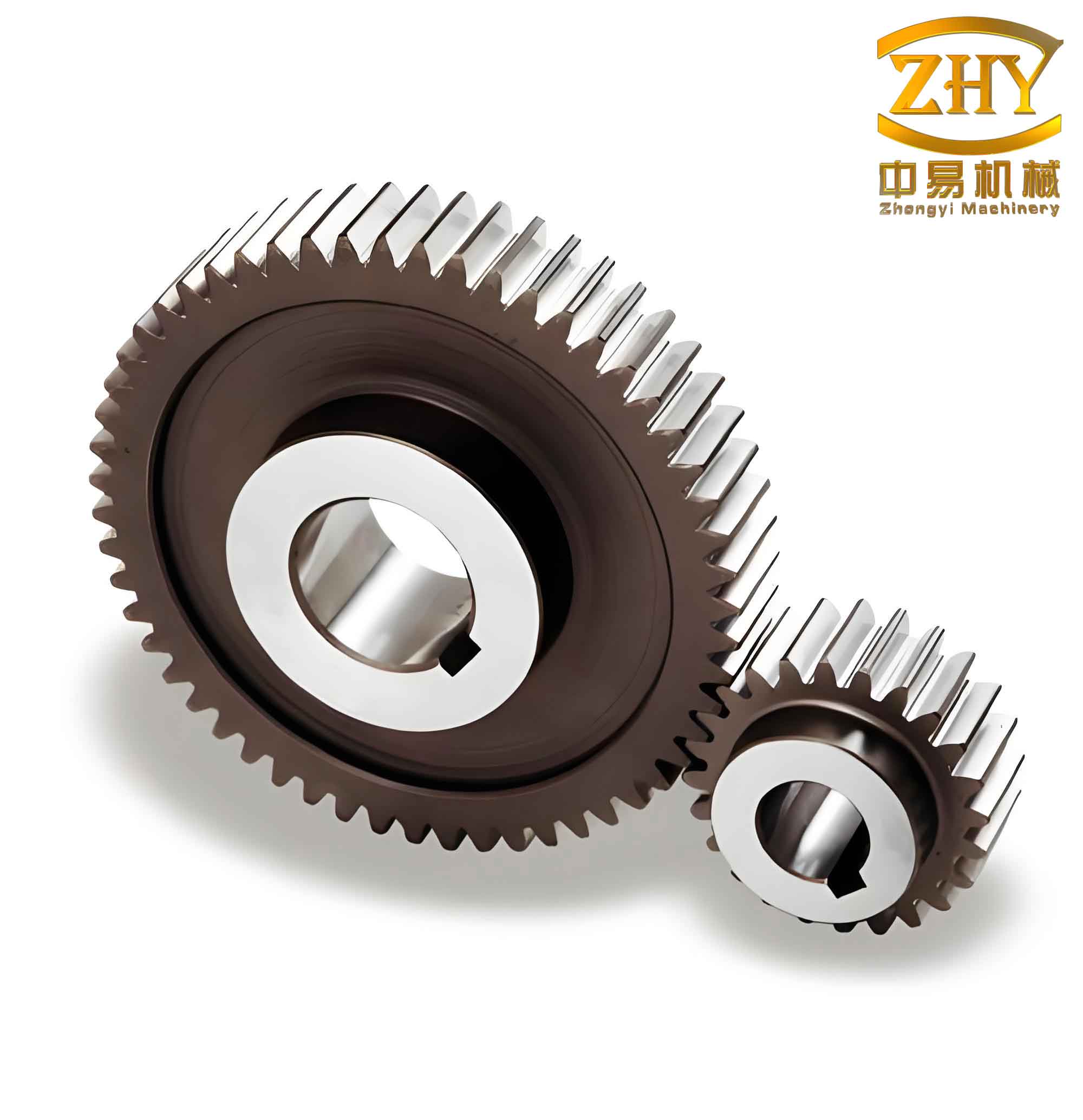
Finite Element Model Setup
In the finite element analysis of the straight spur gear, the boundary conditions were defined as follows: The inner bore of the gear was constrained in the radial direction to simulate the effect of the shaft, while the side faces were constrained in the axial direction (normal to the face). The initial temperature of the entire straight spur gear was set to 860 °C, representing the austenitizing temperature. A two-stage quenching process was simulated:
- Stage 1 – Oil quenching: The gear was immersed in oil at 80 °C with a convective heat transfer coefficient hoil that varied with surface temperature. The time duration was 600 s.
- Stage 2 – Air cooling: After oil quenching, the gear was exposed to ambient air at 25 °C with a constant convective coefficient hair. The cooling continued for 1800 s.
The convective heat transfer coefficient for oil was defined as a piecewise function of temperature, as given in Table 2.
| Temperature (°C) | hoil (W/m²·K) |
|---|---|
| 100 | 2500 |
| 300 | 1800 |
| 500 | 1200 |
| 700 | 800 |
| 860 | 600 |
The governing equation for transient heat conduction in the straight spur gear is given by the Fourier law:
$$ \rho c_p \frac{\partial T}{\partial t} = \nabla \cdot (k \nabla T) $$
where ρ is density, cp is specific heat, k is thermal conductivity, T is temperature, and t is time. The thermal boundary condition at the surface is:
$$ -k \frac{\partial T}{\partial n} = h (T – T_\infty) $$
with h being the convective coefficient and T∞ the ambient temperature (80 °C for oil, 25 °C for air).
Temperature Field Results
During quenching, the temperature distribution inside the straight spur gear was highly non-uniform. At the early stage (t = 10 s), the core region near the inner bore remained at nearly 860 °C, while the outer tooth surfaces dropped to approximately 400 °C. This difference arises because the outer surfaces have larger contact area with the quenching medium, leading to faster heat extraction. As time progressed, the temperature gradient gradually decreased. At t = 60 s, the maximum temperature in the gear was about 410 °C; by t = 600 s, it fell to 79 °C; and at the end of air cooling (t = 1800 s), the maximum temperature was around 74.5 °C. Notably, the larger gear consistently exhibited a slightly higher temperature than the pinion due to its greater thermal mass. The radial temperature variation along the tooth profile is summarized in Table 3 (averaged values for the pinion).
| Radial position (mm from inner bore) | t = 10 s (°C) | t = 60 s (°C) | t = 600 s (°C) | t = 1800 s (°C) |
|---|---|---|---|---|
| 0 (inner) | 860 | 410 | 79 | 74.5 |
| 5 | 720 | 380 | 77 | 73.8 |
| 10 | 580 | 350 | 75 | 73.0 |
| 15 | 460 | 320 | 73 | 72.2 |
| 20 (tooth tip) | 400 | 295 | 71 | 71.5 |
I observed that the radial temperature gradient was steepest at the beginning of quenching and gradually flattened as the system approached thermal equilibrium. This behavior is critical for the development of thermal strains and subsequent residual stresses.
Residual Stress Evolution
The thermal and transformation-induced strains during quenching lead to the build-up of residual stresses. In the straight spur gear, I tracked the von Mises equivalent stress along the radial direction at different time instances. During the first 600 s (oil quenching phase), the outer regions of the gear exhibited higher stress than the inner regions because the faster cooling rate created a greater temperature gradient and earlier martensitic transformation. After 600 s, when the gear was transferred to air cooling, the trend reversed: the inner core continued to cool slowly and underwent phase transformation later, causing compressive stresses to develop near the surface and tensile stresses in the core. The radial stress profiles for the straight spur gear are given in Table 4.
| Radial position (mm) | t = 100 s | t = 200 s | t = 600 s | t = 1800 s |
|---|---|---|---|---|
| 0 (inner) | 350 | 280 | 210 | 950 |
| 5 | 420 | 350 | 290 | 880 |
| 10 | 510 | 440 | 380 | 800 |
| 15 | 620 | 550 | 480 | 720 |
| 20 (tooth tip) | 700 | 630 | 560 | 650 |
To further quantify the overall stress evolution, I plotted the maximum von Mises stress inside the entire straight spur gear as a function of time. The stress initially rose sharply, reaching a peak of approximately 1150 MPa at around 50 s. This peak corresponds to the period when the outer surface had already transformed to martensite while the core was still austenitic, generating severe thermal stresses. Afterwards, the stress decreased to about 800 MPa at 200 s, followed by a second increase to nearly 1200 MPa at 500 s. This second rise is attributed to the phase transformation of the core region, which expanded and interacted with the already hardened surface layer. Finally, after 600 s, the stress gradually stabilized, and at the end of the simulation (t = 1800 s), the maximum residual stress in the straight spur gear was approximately 1.2 GPa.
Discussion and Concluding Remarks
Through this numerical study on a straight spur gear, I obtained valuable insights into the quenching residual stress mechanism. The key findings are:
- The temperature distribution along the radial direction of a straight spur gear decreases monotonically from the inner bore to the tooth tip. The gradient is largest in the early quenching stage and diminishes as the gear cools.
- The residual stress distribution in the straight spur gear exhibits a reversal trend between the oil quenching and air cooling stages. During the first stage, the outer surface is under compressive stress while the inner core is tensile; after transfer to air, the stress distribution flips due to delayed transformation in the core.
- The maximum stress in the straight spur gear evolves non-monotonically: it first increases rapidly, then drops, then rises again, and finally approaches a stable value. This complex behavior is a direct consequence of the interplay between thermal contraction and volumetric changes from austenite-to-martensite transformation.
I have confirmed that ignoring phase transformation effects in the simulation of a straight spur gear would lead to erroneous stress predictions. Therefore, future studies on quenching of straight spur gears must incorporate coupled thermo-mechanical-metallurgical models. The present work provides a foundation for optimizing quenching parameters to minimize residual stresses and improve the fatigue life of straight spur gears.
In conclusion, the finite element analysis of the straight spur gear under the described quenching protocol successfully captured the transient temperature and stress fields. The methodology can be extended to other gear geometries and heat treatment schedules. The results underscore the importance of considering both thermal and transformation strains when assessing the residual stress state of a straight spur gear after quenching.