
I approach the lifting system of a jack-up offshore platform as a load-path problem first and a transmission problem second. In my experience, the conventional rack and pinion gear lifting system is widely used because it is direct, robust, and well understood. A climbing pinion meshes with a long rack attached to the leg, and the platform is raised or lowered by controlling the torque and speed of the pinion. However, I have also observed that the rack and pinion gear arrangement has practical limits in offshore service: large module teeth, difficult manufacturing, expensive replacement, and fatigue-sensitive roots. For this reason, I compare the conventional rack and pinion gear lifting system with a pin-wheel rack drive. My aim is not to dismiss the rack and pinion gear method but to determine where it remains superior and where a pin-wheel rack drive may offer a better balance of cost, maintainability, and reliability.
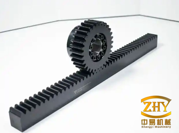
I begin with the observation that a jack-up platform lifting system is not a simple hoist. It must hold the platform in place for long periods, survive storm conditions, transfer wave, current, and wind loads, and still perform controlled jacking when the platform is raised or lowered. The rack and pinion gear unit is therefore a safety-critical connection between the hull and the legs. In my view, any alternative transmission must be judged against the same criteria: strength, stiffness, fatigue life, wear resistance, manufacturability, inspectability, and repair cost.
| Symbol | Meaning | Typical unit |
|---|---|---|
| \(F_t\) | Tangential force at the pitch circle | N |
| \(T\) | Torque on the pinion or pin wheel | N·m |
| \(d\) | Pitch diameter of the driving gear or pin wheel | mm |
| \(b\) | Face width of the rack or gear | mm |
| \(m\) | Module of the rack and pinion gear | mm |
| \(\sigma_H\) | Contact stress | MPa |
| \(\sigma_F\) | Root bending stress | MPa |
| \(d_p\) | Pin diameter in a pin-wheel rack drive | mm |
| \(\phi\) | Rack width coefficient | dimensionless |
| \(\delta\) | Side plate thickness of the pin wheel | mm |
| \(L\) | Pin calculated length | mm |
My starting point. I consider the rack and pinion gear lifting unit as a chain of torque conversion. An electric motor drives a multistage reducer. The reducer may contain parallel-shaft gear pairs and planetary stages. The final output is the climbing pinion, which meshes with the leg rack. In the systems I have studied, the reducer increases torque and reduces speed to a level suitable for jacking. The pinion then converts torque into a linear force along the rack. The linear force supports the platform weight and the dynamic loads transferred from the hull and legs.
I summarize the main components and their functions in the following table. This table reflects the functional view I use when I compare a rack and pinion gear drive with a pin-wheel rack drive.
| Component | Function in rack and pinion gear lifting | What I inspect first |
|---|---|---|
| Drive motor | Provides input speed and torque | Thermal margin, starting torque, braking |
| Reducer | Multiplies torque and reduces speed | Gear stages, bearings, lubrication, backlash |
| Output pinion | Climbing pinion that meshes with the rack | Root condition, flank wear, pitting, alignment |
| Leg rack | Long toothed member attached to the leg | Contact stress, weld condition, straightness |
| Guide and support structure | Maintains mesh alignment and carries reaction loads | Deflection, bolt preload, wear pads |
| Brake and lock | Holds the platform when jacking stops | Holding capacity, redundancy, release reliability |
I have found that the rack and pinion gear system is favored because it can be analyzed with established gear theory. I can calculate contact stress, root bending stress, and scuffing risk using standard formulas. I can also use finite element models to check the leg rack, the pinion, and the supporting structure. However, the same established theory also reveals the limits: as the required load increases, the module must increase, the pinion tooth count may fall, and the root bending stress becomes the dominant design constraint. In many offshore rack and pinion gear designs, the module is very large, sometimes approaching 100 mm, and the pinion may have only seven teeth. This geometry is not easy to manufacture or inspect.
Load path and operating states. I divide the service life of a jack-up lifting system into several states. Each state produces a different combination of static load, dynamic load, and relative motion. The rack and pinion gear mesh experiences all of them.
| Operating state | Dominant load | Motion | Rack and pinion gear concern |
|---|---|---|---|
| Preloading | Leg penetration resistance and hull weight | Intermittent jacking | High torque, low speed, root stress |
| Jacking up | Hull weight plus variable load | Continuous slow motion | Wear, lubrication, flank temperature |
| Jacking down | Controlled lowering load | Continuous slow motion | Back-driving, braking, contact stress |
| Storm holding | Wave, wind, current, dynamic amplification | No motion, small oscillation | Static root stress, fretting, corrosion |
| Transit | Leg weight and inertial loads | Leg raised, no meshing load | Corrosion, impact, alignment |
| Standby | Hull weight and environmental load | No motion | Long-term contact, corrosion, pitting |
In my analysis, the most severe condition is not always the maximum jacking load. Storm holding can produce high static stress at the tooth root for a long duration. During jacking, the same root experiences cyclic stress as teeth enter and leave mesh. The combination of high mean stress and cyclic stress makes the rack and pinion gear root a fatigue-critical location. I therefore treat the pinion root and the rack root as the two locations that define the practical strength limit.
Failure modes of the rack and pinion gear. I have observed four main failure modes in rack and pinion gear lifting units: wear, scuffing or scoring, pitting, and tooth breakage. In offshore service, corrosion and poor lubrication can accelerate all of them. The table below shows how I rank these modes and what I do about each one.
| Failure mode | Mechanism | Consequence | My design or maintenance response |
|---|---|---|---|
| Flank wear | Abrasion, adhesion, contamination | Lost tooth thickness, increased backlash, noise | Hardened flanks, clean lubricant, inspection interval |
| Scuffing | Local welding and tearing under high pressure and sliding | Rapid surface damage, vibration | Correct lubricant, surface finish, load control |
| Pitting | Contact fatigue below the surface | Spalling, stress concentration, vibration | Contact stress limit, material cleanliness, profile control |
| Root fatigue | Cyclic bending at the tooth root | Crack growth and tooth fracture | Root bending limit, fillet optimization, shot peening |
| Corrosion | Salt water and humid marine air | Reduced section, pit initiation | Coating, sealing, rinsing, material selection |
Among these, I consider root fatigue and fracture to be the most dangerous. A worn flank can be monitored and repaired, but a broken tooth in a rack and pinion gear system can cause loss of load path and may require replacement of a large component. In offshore service, replacement of a leg rack is extremely costly. Replacement of a climbing pinion is less costly but still requires access, lifting, and alignment work. Therefore, I design with the intention that the pinion should be the sacrificial component, while the rack should be protected. This is a key conclusion in my comparison.
Root bending as the strength limit. I use the maximum root bending stress as the strength limit of the lifting system. The reason is simple: the root is where a fatigue crack can grow to fracture. I express the general bending check as follows.
$$ \sigma_F = \frac{F_t}{b m} Y_{Fa} Y_{Sa} Y_{\epsilon} Y_{\beta} K_A K_V K_{F\beta} \le \sigma_{FP} $$
Here \(Y_{Fa}\) is the form factor, \(Y_{Sa}\) is the stress correction factor, \(Y_{\epsilon}\) is the contact ratio factor, \(Y_{\beta}\) is the helix angle factor, and the \(K\) terms account for application, dynamic, and face load effects. I do not rely on a single nominal stress. Instead, I compare the calculated root stress with the allowable stress for the material, the heat treatment, and the required safety factor.
For the rack and pinion gear contact, I also check the surface durability. A typical contact stress expression is shown below.
$$ \sigma_H = Z_E \sqrt{\frac{F_t}{b d_1}\frac{u+1}{u}K_A K_V K_H K_{H\beta}} \le \sigma_{HP} $$
In my experience, the contact stress on the rack face can be very high because the rack is long and the load is concentrated over a limited number of teeth. However, the root bending stress often controls the final size of the pinion. When the module is already very large, further increasing the module to reduce root stress creates manufacturing and weight penalties. This is one of the reasons I look for an alternative transmission.
Representative rack and pinion gear data. I use a representative offshore lifting unit to show the stress distribution I have observed. The material and geometry are summarized in the table below. I present the values as a design reference, not as a recommendation for a specific platform.
| Parameter | Climbing pinion | Leg rack |
|---|---|---|
| Material | SAE 4340 | ASTM A514 CrQ |
| Module, mm | 97 | 97 |
| Number of teeth | 7 | 97 |
| Face width, mm | 200 | 240 |
| Yield limit, MPa | 745 | 805 |
| Ultimate strength, MPa | 940 | 890 |
I have recorded the maximum stress at three mesh positions during operation. The results show that the rack contact stress is always the largest local stress, but the pinion root stress can exceed the pinion contact stress at some positions. This means that the design cannot be based only on contact stress. I must check both root bending and contact fatigue, and I must decide which component is allowed to wear or fail first.
| Mesh position | Pinion root max stress, MPa | Pinion contact max stress, MPa | Rack root max stress, MPa | Rack contact max stress, MPa |
|---|---|---|---|---|
| Position A | 618 | 824 | 611 | 1700 |
| Position B | 737 | 691 | 460 | 1440 |
| Position C | 895 | 653 | 336 | 1310 |
I interpret these values as follows. The rack contact stress is the highest, so the rack face is a critical wear and pitting location. However, the pinion root stress rises to 895 MPa at position C, which is higher than the pinion contact stress at that position. Because root fatigue can lead to tooth fracture, I treat the maximum root bending stress as the strength limit of the lifting system. I also note that the rack is welded or attached to the leg and is much more expensive to replace than the pinion. Therefore, in practical design, I usually set the design limit by the service life of the climbing pinion, while ensuring that the rack remains protected.
$$ \sigma_{F,\max} = \max\left(\sigma_{F,\text{pinion root}},\sigma_{F,\text{rack root}}\right) $$
$$ \sigma_{H,\max} = \max\left(\sigma_{H,\text{pinion contact}},\sigma_{H,\text{rack contact}}\right) $$
My design rule is therefore not simply “keep stress below allowable.” It is “keep the rack below its allowable contact and root stress for the full life, and allow the pinion to be the inspected and replaceable element.” This rule shapes my comparison with the pin-wheel rack drive.
Limitations I have observed in rack and pinion gear lifting. The rack and pinion gear system has been used successfully, but I have seen several limitations that are difficult to eliminate. I list them in the table below because they define the motivation for exploring a pin-wheel rack drive.
| Limitation | Why it occurs | Effect on offshore lifting |
|---|---|---|
| Very large module | High torque and low speed require large tooth size | Large reducers, heavy structures, large machining equipment |
| Few pinion teeth | Large module and limited pinion diameter | High root stress, undercut risk, sensitive alignment |
| Difficult manufacturing | Large gear grinding and hobbing machines are required | Few suppliers, long lead time, high cost |
| Expensive replacement | Pinion is a single large component | Long downtime, heavy lifting, realignment |
| Open gearing | Rack is long and exposed to marine environment | Corrosion, contamination, poor lubrication |
| Fatigue-sensitive roots | High cyclic bending at the root | Risk of tooth fracture, need for frequent inspection |
| Contact stress concentration | Misalignment and leg deflection | Pitting, scuffing, edge loading |
I have also observed that the manufacturing cost is not only a function of the pinion. The rack must be machined over a long length, and the leg structure must be prepared for welding or bolting. The alignment between the pinion and the rack is critical. If the leg deflects under load, the contact pattern shifts, and the edge of the tooth may carry a disproportionate share of the load. In a large module rack and pinion gear, this edge loading can be severe. I can improve it with lead crowning and careful support design, but I cannot eliminate it completely.
Pin-wheel rack drive concept. I now consider a pin-wheel rack drive as an alternative. In this arrangement, the driving member is not a solid involute pinion. Instead, it is a pin wheel with cylindrical pins arranged around a circle. The pins mesh with a specially shaped rack. The pin wheel acts as the climbing member, and the rack is attached to the leg. The torque is still converted into a linear force, but the tooth contact is replaced by pin-to-rack contact. This changes the failure mode, the manufacturing method, and the maintenance strategy.
The pin-wheel rack drive is a special form of rack and pinion gear transmission. It retains the direct load path of a rack and pinion gear system, but it replaces the involute tooth with a pin and a matching rack profile. I find this attractive for offshore lifting because the pins are simple cylindrical parts. They can be manufactured on ordinary machine tools, heat treated individually, and replaced one by one if damaged. The pin wheel itself can be built from side plates and pins, so the large and difficult gear cutting operation is avoided.
Why pin-wheel rack drives fit heavy, slow, offshore duty. The operating envelope of a pin-wheel rack drive matches the offshore lifting duty. I have summarized the typical values below.
| Parameter | Typical pin-wheel rack drive range | Offshore lifting relevance |
|---|---|---|
| Peripheral speed | 0.05–0.5 m/s | Jacking speed is very low |
| Transmission ratio | 5–30 | Can be combined with a reducer |
| Efficiency without lubrication | 0.90–0.93 | Acceptable for slow, heavy drives |
| Efficiency with lubrication | 0.93–0.95 | Good when maintenance is planned |
| Load capacity | Heavy and impact tolerant | Suitable for preloading and storm holding |
| Environment tolerance | Dust, water, poor lubrication | Matches marine and offshore conditions |
I have seen pin-wheel drives used in metallurgy, chemical plants, mining, and heavy lifting equipment. They are often chosen for low speed, high load, and harsh environments. These are exactly the conditions of a jack-up lifting system. Therefore, I consider the pin-wheel rack drive a serious candidate, not a novelty.
Pin structure and load path. In a common pin-wheel design, each pin is mounted between two side plates. The pin is supported at both ends, so it behaves like a simply supported beam rather than a cantilever. This is an important mechanical advantage. A cantilever tooth root experiences high bending moment at the root. A simply supported pin distributes the load between two supports and reduces the maximum bending moment for the same load. The pin is also a separate part, so it can be replaced without replacing the entire wheel.
The load path in a pin-wheel rack drive is as follows. The reducer applies torque to the pin wheel. The pin wheel transfers force through one or more pins to the rack. The rack converts the tangential force into a linear force along the leg. The reaction is carried by the pin wheel bearings and the support structure. Because the pins are cylindrical, the contact geometry is known, and I can calculate contact stress and bending stress with relatively simple formulas.
Pin sleeve improvement. A plain pin can suffer from sliding friction when it enters and leaves the rack tooth. The relative motion at the tip of the rack tooth can cause wear and reduce efficiency. To address this, I use a pin with a sleeve. The sleeve is a cylindrical shell that fits over the pin. The pin acts as a core shaft, and the sleeve rotates around it. When the sleeve contacts the rack, the relative motion between the sleeve and the rack is reduced, and the sliding friction is replaced by near-rolling contact between the sleeve and the pin. This reduces wear and extends the life of both the pin and the rack.
| Feature | Plain pin | Pin with sleeve |
|---|---|---|
| Contact with rack | Sliding and rolling mix | Mostly rolling at the sleeve interface |
| Wear location | Pin surface and rack face | Sleeve surface and rack face |
| Replaceable element | Entire pin | Sleeve, then pin if needed |
| Friction loss | Higher | Lower |
| Maintenance | Pin replacement | Sleeve replacement with less downtime |
I prefer the sleeved pin for offshore lifting because it gives me a sacrificial wear surface. The sleeve can be made from a bearing material or a hardened steel, and it can be replaced during a planned maintenance window. The pin core remains protected and can be inspected without removing the entire pin wheel.
Strength and geometry formulas for pin-wheel rack drives. I use the following formulas when I size a pin-wheel rack drive. They are adapted from general pin drive design practice. I present them in a form that I can use for preliminary design and checking.
The pin diameter is selected from contact strength:
$$ d_p \ge \frac{310}{\sigma_{HP}}\sqrt{\frac{F_1}{\phi}} $$
The contact strength is checked by:
$$ \sigma_H = \frac{310}{d_p}\sqrt{\frac{F_1}{\phi}} \le \sigma_{HP} $$
The pin bending strength is checked by:
$$ \sigma_{F2} = \frac{2.5 F_1}{d_p^3}\left(L-\frac{b}{2}\right) \le \sigma_{F2p} $$
The side plate extrusion strength is checked by:
$$ \sigma_{pr} = \frac{F_1}{2 d_p \delta} \le \sigma_{prp} $$
For steel Q235, I use an allowable extrusion stress of approximately 98 to 118 MPa. When the pin wheel and the rack are made of different materials, I take the smaller allowable contact stress for the contact check. At the pitch point, I use the following contact curvature values for preliminary calculation:
$$ \rho_1 = 1.5 d_p $$
$$ \rho_2 = 0.5 d_p $$
These formulas show why the pin-wheel rack drive is attractive. The pin diameter appears directly in the contact and bending equations. I can increase the pin diameter to reduce contact stress and bending stress. I can also increase the number of pins in mesh to share the load. In a rack and pinion gear, I cannot easily increase the number of teeth in contact without changing the module and the whole geometry. In a pin-wheel rack drive, I have more freedom to adjust pin diameter, pin length, side plate thickness, and pin number.
Rack tooth profile for pin-wheel drives. The motion smoothness of a pin-wheel rack drive depends on the rack tooth profile. I have considered three main profiles: straight, circular, and cycloidal. Each has a different effect on the center velocity of the pin wheel. I summarize my comparison below.
| Rack tooth profile | Motion characteristic | Advantage | Limitation |
|---|---|---|---|
| Straight profile | Velocity drop when pins alternate | Simple to manufacture | Velocity fluctuation is noticeable |
| Convex circular profile | Smaller velocity fluctuation than straight | Better motion than straight | Still a sudden change at pin transfer |
| Concave circular profile | Continuous but small velocity fluctuation | Smoother motion, good for limited pin count | More difficult to machine than straight |
| Cycloidal profile | Distinct single and double tooth contact zones | Load sharing in double contact zone | Load jump at transition, complex profile |
In my analysis, the concave circular profile is often the best compromise for offshore lifting when the pin count cannot be increased and when weight and volume must be controlled. The straight profile is the simplest and may be acceptable for very low speed and short travel, but I expect more velocity fluctuation and more impact at pin entry. The cycloidal profile can provide good load sharing, but the transition between single and double contact zones produces a load jump. If I use a cycloidal profile, I must carefully design the transition and the pin stiffness.
Comparison of rack and pinion gear and pin-wheel rack drive. I now compare the two transmission types directly. The table below is the core of my analysis. I use it to decide whether a pin-wheel rack drive is feasible for a given offshore platform.
| Item | Rack and pinion gear | Pin-wheel rack drive |
|---|---|---|
| Structure | Simple and widely understood | Slightly more complex, but modular |
| Transmission efficiency | High | Lower |
| Volume for same torque | Smaller driving gear diameter | Larger pin wheel diameter |
| Weight | Lighter for the driving member | Heavier pin wheel and supports |
| Tooth or pin loading | Cantilever tooth root | Simply supported pin |
| Lubrication | Convenient if enclosed, difficult if open | Slightly poorer but tolerable |
| Repair cost | High; pinion replaced as a whole | Low; individual pins or sleeves replaced |
| Manufacturing cost | High; large gear cutting and grinding | Lower; cylindrical pins and plates |
| Inspection | Requires gear inspection experience | Easy visual and dimensional pin inspection |
| Fatigue critical location | Tooth root | Pin bending and contact |
| Shock tolerance | Moderate | Good |
| Corrosion response | Flank and root corrosion | Pin and sleeve corrosion, replaceable |
I do not conclude that one system is universally better. Instead, I conclude that the pin-wheel rack drive has a different cost and failure profile. The rack and pinion gear is more efficient and more compact at the driving member. The pin-wheel rack drive is easier to manufacture and repair, and its pins are loaded in a more favorable simply supported manner. For offshore platforms where maintenance access is difficult and replacement cost is high, the pin-wheel rack drive may be the better choice. For platforms where efficiency and compactness are dominant, the rack and pinion gear may remain preferable.
Feasibility analysis. I judge feasibility by five criteria: strength, fatigue, motion control, maintainability, and cost. I discuss each one below.
Strength: I can size the pin diameter using the contact and bending formulas. The pin is supported at both ends, so the bending moment is lower than a cantilever tooth root for the same load. I can also use multiple pins in contact to share the load. This gives me confidence that a pin-wheel rack drive can meet the same load capacity as a rack and pinion gear.
Fatigue: The pin experiences cyclic bending as it enters and leaves mesh. The stress amplitude depends on the load per pin and the number of pins sharing the load. I can reduce the stress amplitude by increasing the pin diameter, increasing the number of pins, or reducing the load per pin through load sharing. The pin root is not a sharp fillet in the same way as a gear tooth root, so the stress concentration factor is lower. However, I must still check the pin fillet, the sleeve, and the side plate hole.
Motion control: The pin-wheel rack drive can produce smooth motion if the rack profile is chosen correctly. The concave circular profile gives continuous but small velocity fluctuation. If I need extremely smooth motion, I can increase the number of pins or use a cycloidal profile with a carefully designed transition. In most jack-up operations, the jacking speed is very low, so small velocity fluctuations are acceptable as long as they do not cause impact or vibration.
Maintainability: This is the strongest advantage in my view. A damaged pin or sleeve can be replaced individually. I do not need to remove the entire pin wheel or the reducer. The rack teeth are also easier to inspect because the contact is open and the pin can be removed for access. In offshore service, this can reduce downtime significantly.
Cost: The pin-wheel rack drive avoids the need for a very large gear cutting machine. The pins can be turned, heat treated, and ground on standard equipment. The side plates can be fabricated and machined. The rack profile may require special machining, but the tooling is generally less complex than a large module gear cutter. I expect lower capital cost and lower repair cost.
Design procedure I would follow. When I evaluate a pin-wheel rack drive for a jack-up platform, I follow a step-by-step procedure. I describe it below.
| Step | Action | Output |
|---|---|---|
| 1 | Define load cases and safety factors | Design load, storm load, fatigue spectrum |
| 2 | Select pin wheel diameter and pin number | Preliminary geometry |
| 3 | Calculate tangential force per pin | \(F_1\) |
| 4 | Check pin contact stress | \(d_p\) and \(\phi\) |
| 5 | Check pin bending stress | \(L\), \(b\), and side plate spacing |
| 6 | Check side plate extrusion | \(\delta\) |
| 7 | Select rack tooth profile | Straight, circular, or cycloidal |
| 8 | Check motion smoothness | Velocity fluctuation |
| 9 | Check bearing and support stiffness | Deflection and alignment |
| 10 | Plan maintenance and inspection | Replacement procedure |
Example preliminary calculation. I present a simplified calculation to show how I use the formulas. I assume a tangential force per pin of 250 kN, a rack width coefficient of 0.8, and an allowable contact stress of 600 MPa. I first estimate the minimum pin diameter.
$$ d_p \ge \frac{310}{600}\sqrt{\frac{250000}{0.8}} $$
$$ d_p \ge 0.5167 \times \sqrt{312500} $$
$$ d_p \ge 0.5167 \times 559.0 \approx 288.8 \text{ mm} $$
I would then round the pin diameter to a practical value, for example 300 mm. Next I check the bending stress. I assume a pin length of 360 mm, a rack width of 240 mm, and a pin diameter of 300 mm.
$$ \sigma_{F2} = \frac{2.5 \times 250000}{300^3}\left(360-\frac{240}{2}\right) $$
$$ \sigma_{F2} = \frac{625000}{27000000}(360-120) $$
$$ \sigma_{F2} = 0.02315 \times 240 \approx 5.56 \text{ MPa} $$
This value is very low compared with typical allowable bending stresses, so the pin diameter is controlled by contact stress rather than bending in this example. I then check the side plate extrusion. I assume a side plate thickness of 80 mm.
$$ \sigma_{pr} = \frac{250000}{2 \times 300 \times 80} = \frac{250000}{48000} \approx 5.21 \text{ MPa} $$
This is also low. The example shows that the contact stress is the primary constraint for the pin diameter. In a real design, I would also include dynamic factors, load sharing factors, and safety factors. I would also check the pin wheel bearing loads and the rack tooth contact stress.
Sensitivity to pin number and load sharing. The load per pin is not always equal. Manufacturing tolerances, pin stiffness, rack profile errors, and support deflection can cause uneven load sharing. I therefore use a load sharing factor when I calculate the maximum pin force.
$$ F_{1,\max} = K_s \frac{F_{\text{total}}}{n_{\text{eff}}} $$
Here \(K_s\) is the load sharing factor, and \(n_{\text{eff}}\) is the effective number of pins in contact. I usually take \(K_s\) greater than 1 to account for uneven load. If I increase the number of pins, \(n_{\text{eff}}\) increases, and the load per pin decreases. However, increasing the number of pins also increases the pin wheel diameter and the weight. I must find a balance between contact stress, bending stress, and package size.
| Parameter | Effect of increase | Design consequence |
|---|---|---|
| Pin diameter | Reduces contact and bending stress | Increases weight and pin wheel size |
| Number of pins | Reduces load per pin | Increases pin wheel diameter |
| Pin length | Reduces contact stress but increases bending moment | Requires careful optimization |
| Rack width | Reduces contact stress | Increases rack size and weight |
| Side plate thickness | Reduces extrusion stress | Increases weight and cost |
Manufacturing and maintenance comparison. I have seen that the manufacturing route is a major factor in offshore equipment. A large rack and pinion gear requires specialized machines and skilled operators. The lead time can be long, and the cost is high. A pin-wheel rack drive uses pins that can be produced in batches. The side plates can be flame cut, machined, and assembled. The rack profile still requires machining, but the tooling is simpler. In maintenance, a pin-wheel rack drive allows me to replace a single pin or sleeve. I can also rotate the pins to distribute wear. In a rack and pinion gear, I cannot replace a single tooth. I must replace the entire pinion or repair the rack in place, which is much more difficult.
| Activity | Rack and pinion gear | Pin-wheel rack drive |
|---|---|---|
| Primary machining | Large gear hobbing and grinding | Turning and grinding of pins |
| Special tooling | Large module cutters | Standard pin tools and profile cutters |
| Assembly | Gear mounted on shaft | Pins mounted between side plates |
| Wear part replacement | Entire pinion | Individual pin or sleeve |
| Inspection access | Limited by enclosure | Open pin inspection |
| Spare parts | Large, expensive pinion | Small, low-cost pins and sleeves |
Fatigue and life assessment. I use a fatigue spectrum for the rack and pinion gear and for the pin-wheel rack drive. The spectrum includes jacking cycles, storm holding, and transit. For the pin-wheel rack drive, the critical location is the pin at the side plate hole and the pin at the contact with the rack. I check the nominal bending stress, the stress concentration at the hole, and the contact stress. I also check the sleeve for wear and the side plate for bearing stress.
$$ \sigma_a = \frac{\sigma_{\max}-\sigma_{\min}}{2} $$
$$ \sigma_m = \frac{\sigma_{\max}+\sigma_{\min}}{2} $$
$$ \frac{\sigma_a}{\sigma_{-1}} + \frac{\sigma_m}{\sigma_y} \le \frac{1}{n} $$
In my assessment, the pin-wheel rack drive can achieve a long fatigue life if the load sharing is good and the stress concentration at the side plate is controlled. I can improve the fatigue life by shot peening the pin, using a generous fillet at the side plate hole, and selecting a material with good toughness. I can also use a sleeve to protect the pin from wear and to reduce the stress concentration at the contact point.
Corrosion and marine environment. I cannot ignore corrosion. The rack and pinion gear is open to salt spray, rain, and sea water. The pin-wheel rack drive has the same exposure. However, the pin-wheel rack drive has an advantage: the pins and sleeves can be removed and replaced. I can also use corrosion-resistant coatings, stainless sleeves, or sealed lubrication. In a rack and pinion gear, corrosion pits on the tooth flank can initiate pitting and fatigue cracks. In a pin-wheel rack drive, corrosion on a pin can be detected and the pin can be replaced before it causes a major failure.
| Corrosion factor | Rack and pinion gear | Pin-wheel rack drive |
|---|---|---|
| Exposed surface | Tooth flanks and roots | Pins, sleeves, rack teeth |
| Inspection difficulty | High for root and flank | Moderate; pins can be removed |
| Repair method | Weld repair or replacement | Pin or sleeve replacement |
| Coating options | Limited by contact stress | Can use coated sleeves |
| Consequence of pitting | Stress concentration and crack initiation | Local pin wear, replaceable |
Comparison of design limits. I return to the design limit question because it determines the size and cost of the system. For the rack and pinion gear, I use the maximum root bending stress as the strength limit. I also use the contact stress to prevent pitting. In practice, the pinion life is the design limit because the pinion is the replaceable component, and the rack must be protected. For the pin-wheel rack drive, I use the pin contact stress and pin bending stress as the design limits. The pin is the replaceable component, and the rack must be protected. The logic is the same: protect the expensive long member, and allow the smaller member to be replaced.
| Design limit | Rack and pinion gear | Pin-wheel rack drive |
|---|---|---|
| Primary strength limit | Maximum root bending stress | Pin contact stress and pin bending stress |
| Secondary limit | Contact stress | Side plate extrusion stress |
| Protected component | Leg rack | Leg rack |
| Replaceable component | Climbing pinion | Pin and sleeve |
| Design life basis | Pinion service life | Pin and sleeve service life |
Practical recommendations. I recommend the following when considering a pin-wheel rack drive for a jack-up offshore platform. First, I would use a pin with a sleeve to reduce sliding wear. Second, I would choose a concave circular rack profile if smooth motion is required and the pin count is limited. Third, I would design the side plates and pin holes for fatigue, not just static bearing stress. Fourth, I would include a load sharing factor in the pin force calculation. Fifth, I would provide access for pin inspection and replacement. Sixth, I would protect the rack with a hardened surface or a replaceable rack segment if possible. Seventh, I would validate the design with a full-scale or sub-scale test that includes misalignment and corrosion effects.
I would also keep the rack and pinion gear option in the evaluation. If the platform has a small lifting load, a compact envelope, and a high requirement for efficiency, the rack and pinion gear may still be the best choice. If the platform has a very large lifting load, long leg travel, difficult maintenance access, and a need to reduce manufacturing cost, the pin-wheel rack drive becomes more attractive. My comparison is therefore conditional, not absolute.
Economic perspective. I have found that the economic argument for the pin-wheel rack drive is strong in offshore applications. The initial cost of a large rack and pinion gear is high because of the special machining. The repair cost is also high because the pinion is a single large part. The pin-wheel rack drive has lower initial cost and much lower repair cost. The operating cost may be slightly higher because the efficiency is lower, but the jacking speed is low and the operating hours are limited. The maintenance cost is lower because pins and sleeves can be replaced individually. In my view, the life-cycle cost of the pin-wheel rack drive can be lower than the rack and pinion gear in many offshore lifting applications.
| Cost category | Rack and pinion gear | Pin-wheel rack drive |
|---|---|---|
| Initial manufacturing | High | Moderate |
| Special equipment | Required | Limited |
| Spare parts | Expensive pinion | Low-cost pins and sleeves |
| Downtime for repair | Long | Short |
| Operating efficiency | High | Lower |
| Life-cycle cost | Often high | Often lower |
Risk and mitigation. I also consider the risks of the pin-wheel rack drive. The main risks are uneven load sharing, pin seizure in the side plate, rack profile error, and motion fluctuation. I mitigate these risks by using a load sharing factor, lubricated or coated pin holes, precise rack machining, and a profile that minimizes velocity fluctuation. I also recommend a prototype test that measures pin strain and rack contact pattern under load. If the test shows acceptable load sharing, the design can proceed.
| Risk | Cause | Mitigation |
|---|---|---|
| Uneven pin load | Tolerance and deflection | Load sharing factor, flexible support, precision machining |
| Pin seizure | Corrosion, poor lubrication | Coated pin holes, sealed lubrication, inspection |
| Rack profile error | Machining and alignment | Profile grinding, alignment check, trial mesh |
| Motion fluctuation | Tooth profile and pin transfer | Concave circular or cycloidal profile, more pins |
| Pin fatigue | Cyclic bending | Large pin diameter, shot peening, fillet optimization |
Final assessment. I have analyzed the rack and pinion gear lifting system and the pin-wheel rack drive from the perspective of offshore jack-up platform operation. My analysis confirms that the rack and pinion gear is a mature and efficient transmission, but it has practical limits: large module, few teeth, high root stress, difficult manufacturing, and expensive repair. I have also shown that the pin-wheel rack drive is a feasible alternative. It uses simple cylindrical pins, it is easy to manufacture and repair, it distributes load through simply supported pins, and it can be adapted to the low-speed, heavy-load, harsh environment of offshore lifting. The key design limits are pin contact stress and pin bending stress, while the rack remains the protected component. I therefore conclude that the pin-wheel rack drive deserves serious consideration in the further development of offshore lifting systems, especially where life-cycle cost, maintainability, and manufacturing simplicity are important.
In my future work, I would combine the rack and pinion gear and pin-wheel rack drive models into a single optimization framework. I would use the rack and pinion gear for its efficiency and compactness where it is superior, and I would use the pin-wheel rack drive for its maintainability and lower cost where it is superior. I would also develop a test program that compares the two systems under the same load spectrum, corrosion exposure, and misalignment conditions. This would provide the data needed to move from preliminary feasibility to detailed design. My overall conclusion is that the offshore lifting industry can benefit from both transmission types, and the pin-wheel rack drive is a promising path for innovation.