1. Introduction
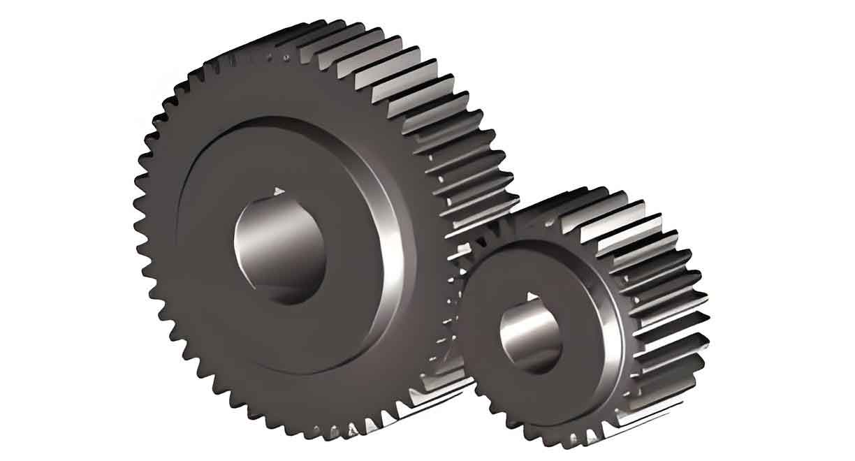
Spur gears, as core components in mechanical transmission systems, are widely recognized for their high transmission precision, power capacity, and compact structure. However, during operation, spur gears are subjected to irregular alternating loads, leading to fatigue failure—particularly root fracture, which poses significant safety risks. Traditional surface strengthening methods, such as shot peening and laser hardening, often suffer from uneven hardening and thermal distortion. To address these limitations, this study introduces ultrasonic rolling technology for spur gear root strengthening. This innovative approach leverages high-frequency vibration impacts to enhance surface integrity and extend fatigue life.

The primary objectives include:
- Developing an ultrasonic rolling device tailored for spur gear roots.
- Establishing mechanical and contact characteristic models.
- Optimizing process parameters for superior surface integrity.
- Investigating the influence of surface characteristics on bending fatigue performance.
2. Literature Review
2.1 Current Surface Strengthening Techniques
Existing methods for gear surface strengthening are summarized in Table 1. While techniques like carburizing and laser hardening improve hardness and residual stress, they often lack precision and consistency. Ultrasonic rolling, with its stable energy transmission and controllable parameters, emerges as a promising alternative.
| Method | Advantages | Disadvantages |
|---|---|---|
| Shot Peening | Improves surface hardness | Uneven coverage, surface roughness |
| Laser Hardening | Deep hardened layer | High cost, thermal distortion |
| Ultrasonic Rolling | Precise control, no heat input | Limited geometric adaptability |
2.2 Ultrasonic Rolling Devices
Recent advancements in ultrasonic rolling devices focus on planar and cylindrical surfaces, but gear root applications remain underexplored. Key challenges include geometric constraints and energy transmission efficiency.
3. Methodology
3.1 Ultrasonic Rolling Device Design
A custom ultrasonic rolling system was developed (Figure 1), comprising:
- Vibration System: A composite horn with a resonance frequency of 30.48 kHz.
- Rolling Head: A spherical tool (radius RT=3 mmRT=3mm) for contact with the spur gear root.
- Control Unit: Integrated with a CNC machine for precise parameter adjustment.
Key Design Equations:
The longitudinal vibration of the horn is governed by:[F3V3]=T[F0V0][V3F3]=T[V0F0]
where TT is the transfer matrix derived from harmonic response analysis.
3.2 Vibration Characteristics
Experiments evaluated the system’s amplitude, frequency, and temperature under varying loads (0–400 N). Results showed:
- Amplitude: Peaked at 8.2 µm under 300 N load.
- Temperature: Remained below 35°C, ensuring thermal stability.
| Load (N) | Amplitude (µm) | Frequency (kHz) | Current (A) |
|---|---|---|---|
| 0 | 6.0 | 30.15 | 0.27 |
| 300 | 8.2 | 31.42 | 0.42 |
| 400 | 7.5 | 30.48 | 0.35 |
4. Mechanical and Contact Models
4.1 Elastic-Plastic Deformation
Using Hertz contact theory, the contact radius aa and bb between the roller and spur gear root were derived:a=1.145nsRTRg2Rg−RT(1−μ12E1+1−μ22E2)3a=1.145ns32Rg−RTRTRg(E11−μ12+E21−μ22)b=1.145nbRTRg2Rg−RT(1−μ12E1+1−μ22E2)3b=1.145nb32Rg−RTRTRg(E11−μ12+E21−μ22)
where RgRg is the gear root radius, and μμ, EE denote Poisson’s ratio and elastic modulus.
4.2 Contact Area Coefficient
The contact area coefficient WW, critical for continuous processing, is defined as:W=2aL⋅W=L2a⋅
where LL is the step distance, and qq is the gear width.
5. Surface Integrity and Parameter Optimization
5.1 Residual Stress and Hardness
Residual stress (σσ) and surface hardness (HH) were measured under varying parameters:
- Residual Stress: Increased with rolling depth (h0h0) and amplitude (A0A0), peaking at −650 MPa−650MPa.
- Hardness: Improved by 51% (from 608 HV to 1051 HV) at h0=0.06 mmh0=0.06mm.
| Parameter | Residual Stress (MPa) | Hardness (HV) | Roughness (µm) |
|---|---|---|---|
| h0=0.03 mmh0=0.03mm | -355 | 743 | 0.65 |
| h0=0.06 mmh0=0.06mm | -647 | 1086 | 0.38 |
5.2 NSGA-Based Optimization
A multi-objective optimization model using NSGA-II yielded Pareto-optimal solutions (Table 2). Key findings:
- Optimal Parameters: h0=0.052–0.056 mmh0=0.052–0.056mm, v=86–94 mm/minv=86–94mm/min, L=0.096–0.13 mmL=0.096–0.13mm, A0=3.17–3.3 µmA0=3.17–3.3µm.
- Trade-offs: Higher efficiency reduced surface integrity by 30%.
6. Bending Fatigue Performance
6.1 Fatigue Life Model
The bending fatigue life NfNf was modeled using fracture mechanics:Δσ(c)=ktΔS2c⋅Rs[1+4cRs−1]Δσ(c)=2cktΔS⋅Rs[1+Rs4c−1]
where cc is the crack length, and ΔSΔS is the stress amplitude.
6.2 Experimental Validation
Fatigue tests demonstrated:
- Ultrasonic Rolling: Extended fatigue life to 3×1063×106 cycles.
- Stress Concentration: Reduced by 3% compared to traditional rolling.
| Condition | Fatigue Life (Cycles) | Crack Initiation Depth (mm) |
|---|---|---|
| Untreated | 1.2×1061.2×106 | 0.12 |
| Ultrasonic Rolling | 3.0×1063.0×106 | 0.43 |
7. Conclusion
- Device Development: The ultrasonic rolling system achieved stable vibration characteristics (amplitude ≤ 8.2 µm, temperature ≤ 35°C).
- Surface Integrity: Optimal parameters enhanced residual stress (−650 MPa−650MPa), hardness (1086 HV), and roughness (0.38 µm).
- Fatigue Life: Ultrasonic rolling increased bending fatigue life by 150%, with crack initiation depth shifting from 0.12 mm to 0.43 mm.
Innovations:
- First application of ultrasonic rolling to spur gear roots.
- NSGA-II-driven parameter optimization for high efficiency and surface quality.
